TC1796
Peripheral Units (Vol. 2 of 2)
Controller Area Network (MultiCAN) Controller
User’s Manual 22-126 V2.0, 2007-07
MultiCAN, V2.0
Note: The number of scheduler entries following a time mark should not exceed the
number of 10. In order to minimize the required accesses to the scheduler memory
by the scheduler control part, the user should set up the system carefully.
22.6.2.2 Scheduler Entry Type Description
Time Mark Entry
A time mark entry is defined as follows:
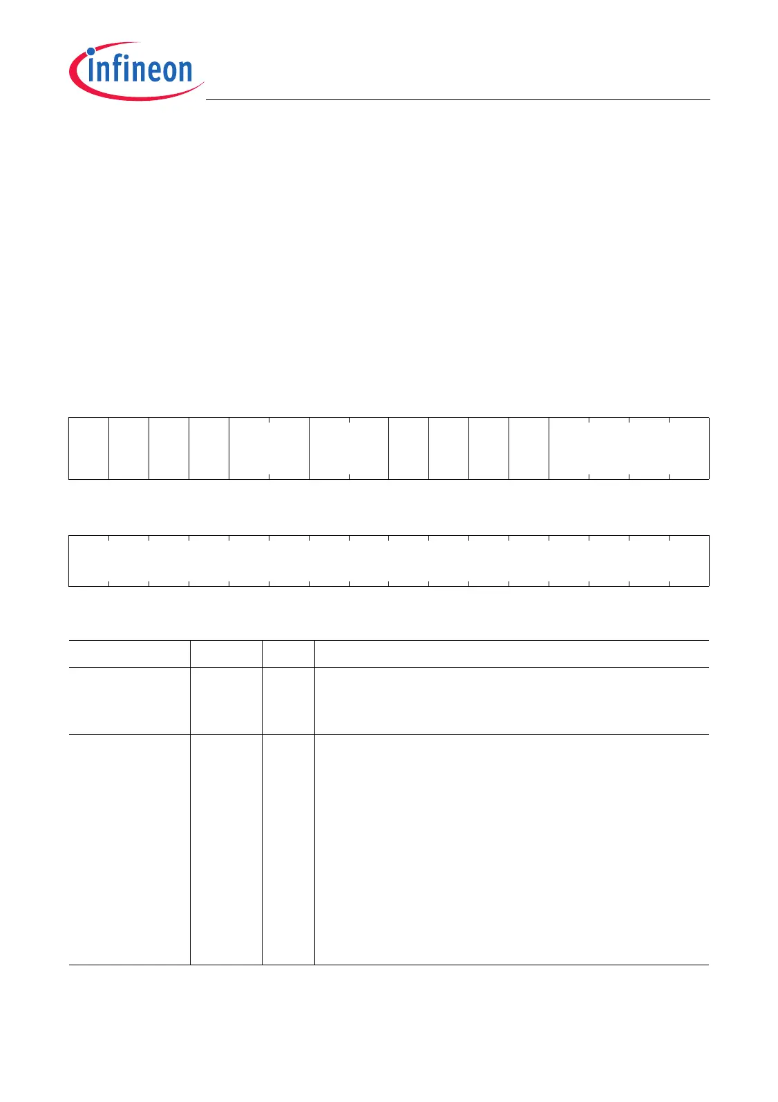
TME
Time Mark Entry
31 30 29 28 27 26 25 24 23 22 21 20 19 18 17 16
0 0 0 1 0 ARBM
IEN
REC
F1
IEN
REC
F0
IEN
TRA
F1
IEN
TRA
F0
INP
rw rw rw rw r rw rw rw rw rw rw
1514131211109876543210
TMV
rw
Field Bits Type Description
TMV
1)
[15:0] rw Time Mark Value
This bit field determines the compare value used for
the next compare action with the cycle time.
INP [19:16] rw Interrupt Node Pointer
INP selects the interrupt output line INT_Om
(m = 0-15) that will be activated when a match is
detected between the cycle time and the time mark
value defined by TMV and if at least one of the four
interrupt conditions is met and enabled.
0000
B
Interrupt output line INT_O0 is selected.
0001
B
Interrupt output line INT_O1 is selected.
…
B
…
1110
B
Interrupt output line INT_O14 is selected.
1111
B
Interrupt output line INT_O15 is selected.
 Loading...