TC1796
System Units (Vol. 1 of 2)
Direct Memory Access Controller
User’s Manual 12-36 V2.0, 2007-07
DMA, V2.0
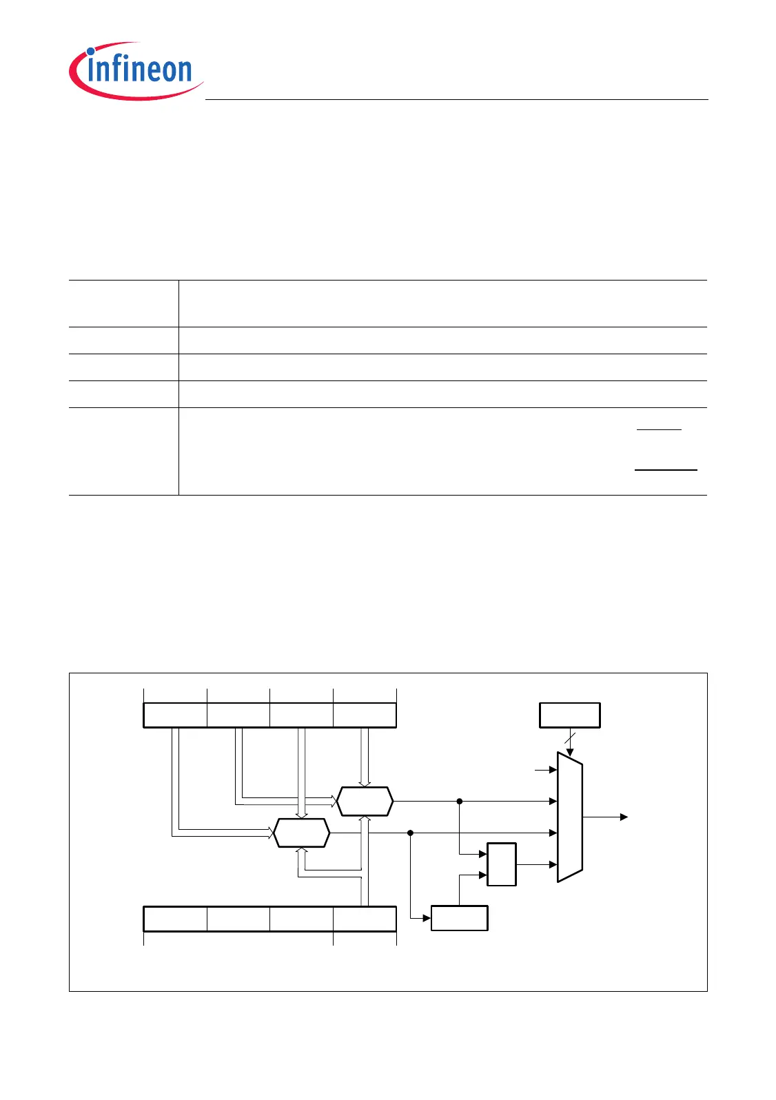
12.1.9.2 Pattern Detection for 8-bit Data Width
When 8-bit channel data width is selected (CHCRmn.CHDW = 00
B
), the pattern
detection logic is configured as shown in Figure 12-25. Three compare match
configurations are possible.
When 8-bit channel data width is selected, the pattern detection logic makes it possible
to compare the byte of one read move with two different patterns. Furthermore, after
each read move the pattern match result “RDm0 with PATm1, masked by PATm3” is
stored in bit CHCRmn.LXO. This operating mode allows, for example, to detect two-byte
sequences in an 8-bit data stream coming from a serial peripheral unit with 8-bit data
width (e.g.: recognition of carriage-return, line-feed characters). A mask operation of
each compared bit is possible.
Figure 12-25 Pattern Detection for 8-bit Data Width (CHCRmn.CHDW = 00
B
)
Table 12-2 Pattern Detection for 8-bit Data Width
CHCRmn.
PATSEL
Pattern Detection Operating Modes
00
B
Pattern detection disabled
01
B
Pattern compare RDm0 to PATm0, masked by PATm2
10
B
Pattern compare RDm0 to PATm1, masked by PATm3
11
B
Pattern compare RDm0 to PATm0, masked by PATm2 of the actual
read move and
Pattern compare RDm0 to PATm1, masked by PATm3 of the previous
read move of DMA channel mn
MCA05702
031 1516
RDm3 RDm2 RDm1 RDm0
31
708
COMP
2
&
PATSEL
CHCRmn
Pattern
Detected
0
LXO
CHSRmn
MEmR
MEmPR
1)
1) Compare result is clocked into LXO after each read move.
Mask
Mask
782324
PATm3 PATm2 PATm0PATm1
COMP
00
01
10
11

 Loading...