TC1796
Peripheral Units (Vol. 2 of 2)
Synchronous Serial Interface (SSC)
User’s Manual 20-30 V2.0, 2007-07
SSC, V2.1
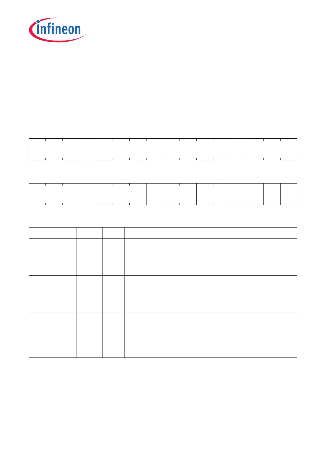
20.2.2 Control Registers
The PISEL register controls the input signal selection of the SSC module. Each input of
the module kernel receive, transmit and clock signals has associated two input lines (port
A and port B).
PISEL
Port Input Select Register (04
H
) Reset Value: 0000 0000
H
31 30 29 28 27 26 25 24 23 22 21 20 19 18 17 16
0
r
1514131211109876543210
0 STIP 0 SLSIS SCIS SRIS
MRI
S
r rw r rw rw rw rw
Field Bits Type Description
MRIS 0rwMaster Mode Receive Input Select
MRIS selects the receive input line in Master Mode.
0
B
Receive input line MRSTA is selected
1
B
Receive input line MRSTB is selected
SRIS 1rwSlave Mode Receive Input Select
SRIS selects the receive input line in Slave Mode.
0
B
Receive input line MTSRA is selected
1
B
Receive input line MTSRB is selected
SCIS 2rwSlave Mode Clock Input Select
SCIS selects the module kernel SCLK input line that is
used as clock input line in Slave Mode.
0
B
Slave Mode clock input line SCLKA is selected
1
B
1Slave Mode clock input line SCLKB is selected

 Loading...