TC1796
Peripheral Units (Vol. 2 of 2)
General Purpose Timer Array (GPTA)
User’s Manual 24-225 V2.0, 2007-07
GPTA, V2.0
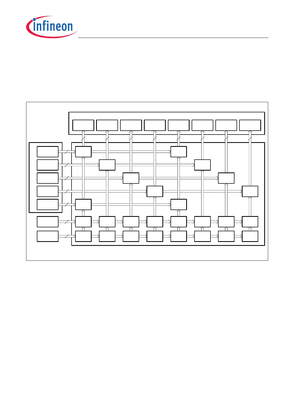
24.4.2.2 LTC Input Multiplexing Scheme
The LTC input multiplexer as shown in Figure 24-77 and Figure 24-80 connects the 40
(= 5 × 8) input lines of the I/O groups, the eight clock bus input lines, or the four PDL input
lines PDL[3:0] and the four internal input lines INT[3:0] with the 64 (= 8 × 8) LTC inputs,
organized in eight LTC groups.
Figure 24-80 LTC Input Multiplexer of LTCA2
LTC
Input
Multiplexer
I/O Groups
MCA05989
LTC Groups
8
IOG0
IOG1
IOG2
IOG3
LIMG
00
LIMG
02
LIMG
03
LIMG
10
LIMG
01
IOG4
PDL[3:0]
INT[3:0]
LTCG0
LTC[07:00]
LTCG1
LTC[15:08]
LTCG2
LTC[23:16]
LTCG3
LTC[31:24]
LTCG5
LTC[47:40]
LTCG6
LTC[55:48]
LTCG7
LTC[63:56]
LTCG4
LTC[39:32]
LIMG
04
LIMG
06
LIMG
07
LIMG
05
LIMG
14
CLK[7:0]
LIMG
40
LIMG
41
LIMG
42
LIMG
30
LIMG
31
LIMG
32
LIMG
33
LIMG
44
LIMG
45
LIMG
46
LIMG
47
LIMG
35
LIMG
36
8
8
8
8
8
8
8 8 8 8 8 8 8 8
LIMG
43
LIMG
37
LIMG
34

 Loading...