TC1796
Peripheral Units (Vol. 2 of 2)
Analog-to-Digital Converter (ADC)
User’s Manual 25-4 V2.0, 2007-07
ADC, V2.0
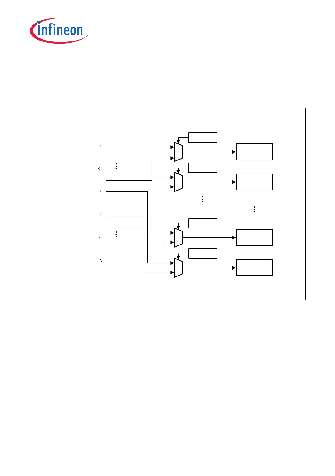
25.1.1 Analog Input Connections
The 32 analog inputs AIN[31:0] of the ADC module are connected to the 16 analog input
channels of the TC1796 via analog input multiplexers. These analog input multiplexers
are shown in Figure 25-3.
Figure 25-3 Analog Input Multiplexer Configuration
Each ADC channel n (n = 0-15) can be connected to two analog inputs: AIN[n] and
AIN[n+16]. The selection is made for ADC channel n by the channel control register
group select bit CHCONn.GRPS. With CHCONn.GRPS = 0, an analog input of analog
input group 0 is selected. With CHCONn.GRPS = 1, an analog input of analog input
group 1 is selected.
MCA06006
AIN0
AIN1
AIN14
AIN15
AIN16
AIN17
AIN30
AIN31
CHCON0
GPRS
ADC
Channel 0
ADC
Channel 1
ADC
Channel 14
ADC
Channel 15
CHCON1
GPRS
CHCON14
GPRS
CHCON15
GPRS
0
1
0
1
0
1
0
1
Analog Input
Group 0
Analog Input
Group 1

 Loading...