TC1796
System Units (Vol. 1 of 2)
System Control Unit
User’s Manual 5-12 V2.0, 2007-07
SCU, V2.0
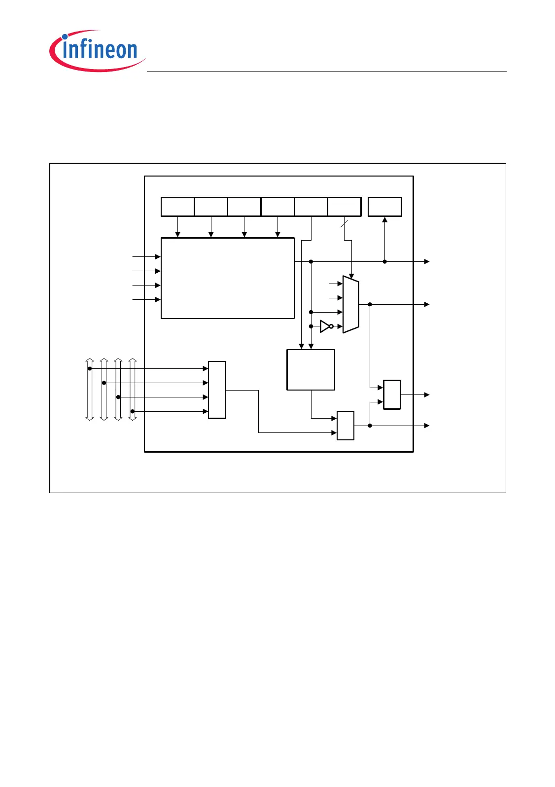
5.3.2 Output Channel
The output channel logic shown in Figure 5-3 is built in for each of the four output
channels.
Figure 5-3 Interrupt Gating Logic (Output Channel y)
The output signals of the output channel y can be used to trigger peripheral actions, DMA
requests, or interrupts.
PDOUTy Output Signal
The pattern detection output PDOUTy can be used to enable/disable peripheral
functions while a certain condition (pattern) is detected (level controlled output).
PDOUTy can be typically used to enable/disable analog-to-digital conversions. The
output PDOUTy is active as long as the programmed condition of input signals (INTFx)
is met.
Each INTFx output signal from input channel x is connected to each output channel y.
Bit IPENy[3:0] determine whether flag INTFx of input channel x takes part in the pattern
detection of output channel y. The output signal PDOUTy is an AND combination of all
INTFx inputs that are enabled by IPENyx = 1. In other words, the PDOUTy signal
MCA05615
IGCRn
IPENy0IPENy1IPENy2IPENy3
PDRR
INTF0
INTF1
INTF2
INTF3
Interrupt Flags
from Input
Channels
PDOUTy
2
01
10
11
00
PDRyIGPy
0
1
GOUTy
INT0y
INT1y
INT2y
INT3y
Pattern
Detection
Logic
x = Number of input channel (x = 0-3)
y = Number of output channel (y = 0-3)
Edge
Detection
&
IOUTy
TOUTy
Input Channel
Outputs
INT0[3:0]
INT1[3:0]
INT2[3:0]
INT3[3:0]
Output Channel y
GEENy
Enable
≥1
≥1

 Loading...