TC1796
System Units (Vol. 1 of 2)
System Control Unit
User’s Manual 5-10 V2.0, 2007-07
SCU, V2.0
The External Request Select unit (ERS) has three parts:
• The External Request Selection unit (ERS) selects one input signal for each input
channel.
• The External Trigger Logic unit (ETL) selects the input channel’s input signal trigger
condition, and provides output signals to the output channel.
• The Interrupt Gating unit (INTG) combines the detected events of the ETL and
provides pattern recognition for each output channel, as well as triggering and gating
functions for A/D converters or DMA controller.
The functional blocks of the ERU are described in detail in the following sections.
5.3.1 Input Channel
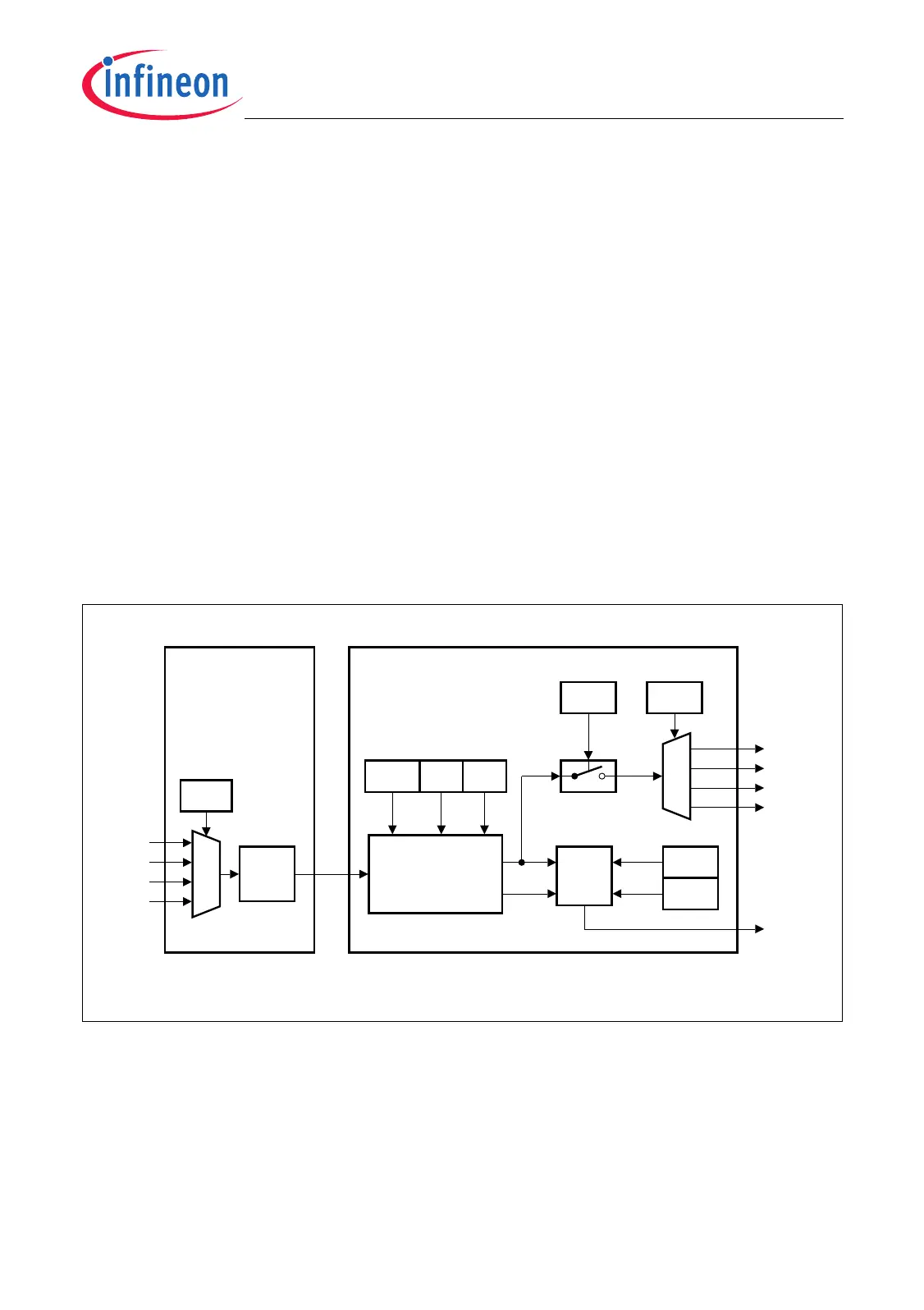
Figure 5-2 shows the basic structure of an input channel. The input channel has two
parts, one part located in the ERS and one part located in the ETL. Two of the four input
channels are always controlled by one External Input Channel Register EICRn (n = 0, 1;
n = 0 applies to input channel 0 and 1, n = 1 applies to input channel 2 and 3). In the
following description, the index number “x” indicates the input channel number.
Figure 5-2 External Request Unit Input Channel
An input channel of the ERS contains an 4-to-1 input multiplexer (controlled by bit field
EICRn.EXISx) that selects one of four possible request input lines INx[3:0]. The selected
signal then becomes synchronized. This is required for further control purposes that are
done in the Event Trigger Logic Unit (ETL) of the input channel.
INTx3
MCA05614
FMR
FSx
FCx
Clear
Set
INx0
INx1
INx2
INx3
Synch.
Stage
EXISx
EICRn
External Request
Selection Unit
(ERS)
Edge
Detection
RENx
EICRn
FENx
INTFx
EIFR
EIENx
EICRn
INPx
EICRn
Event Trigger
Logic Unit
(ETL)
INTx0
INTx1
x = Number of input channel (n = 3-0 )
INTFx
INx
LDE Nx
Set
Clear
INTx2

 Loading...