TC1796
Peripheral Units (Vol. 2 of 2)
Micro Second Channel (MSC)
User’s Manual 21-68 V2.0, 2007-07
MSC, V2.0
2. Additional details of the clock control register functionality are described in section
“Clock Control Register CLC” on Page 3-24 of the TC1796 User’s Manual System
Units part (Volume 1).
21.3.3.2 Fractional Divider Register
The Fractional Divider Registers control the clock rate of the shift clock f
MSC0
and f
MSC1
.
Each MSC module has its own fractional divider register.
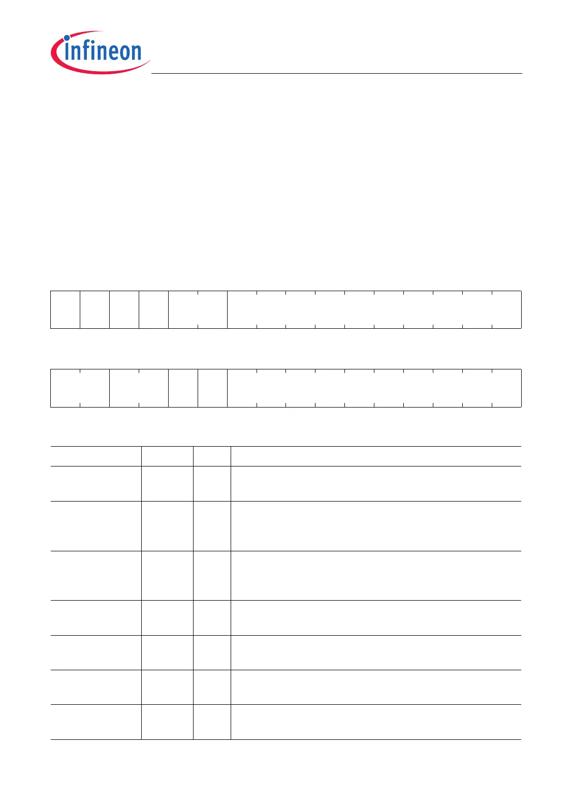
FDR
Fractional Divider Register (0C
H
) Reset Value: 0000 0000
H
31 30 29 28 27 26 25 24 23 22 21 20 19 18 17 16
DIS
CLK
EN
HW
SUS
REQ
SUS
ACK
0RESULT
rwh rw rh rh r rh
1514131211109876543210
DM SC SM 0 STEP
rw rw rw r rw
Field Bits Type Description
STEP [9:0] rw Step Value
Reload or addition value for RESULT.
SM 11 rw Suspend Mode
SM selects between granted or immediate suspend
mode.
SC [13:12] rw Suspend Control
This bit field determines the behavior of the fractional
divider in suspend mode.
DM [15:14] rw Divider Mode
DM selects normal or fractional divider mode.
RESULT [25:16] rh Result Value
Bit field for the addition result.
SUSACK 28 rh Suspend Mode Acknowledge
Indicates state of SPNDACK signal.
SUSREQ 29 rh Suspend Mode Request
Indicates state of SPND signal.

 Loading...