TC1796
System Units (Vol. 1 of 2)
General Purpose I/O Ports and Peripheral I/O Lines
User’s Manual 10-81 V2.0, 2007-07
Ports, V2.0
10.13 Port 10 (Hardware Select Inputs)
This section describes the Port 10 functionality in detail.
10.13.1 Port 10 Configuration
Port 10 is a 4-bit input-only port. Its pins are used for hardware configuration as
HWCFG[3:0] lines. The logic levels of the four Port 10 lines are latched when the
hardware reset goes inactive (at the rising edge of HDRST) and can be checked by
software by reading bit field HWCFG in the reset status register RTS_SR. The four input
lines of Port 10 have weak pull-up devices connected (always active).
Inside the TC1796, the HWCFG[3:0] lines are used for boot configuration selection. Input
P10.1 (HWCFG1) operates as emergency stop input for the GPTA modules. The
emergency stop control logic is described in detail in the “System Control Unit” chapter
(Page 5-57) of this User’s Manual.
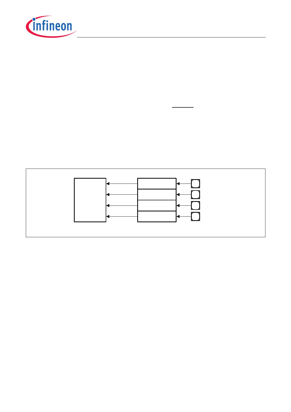
Figure 10-14 Port 10 Configuration Diagram
MCA05665
P10.3 Control
P10.2 Control
P10.1 Control
P10.0 Control P10.0
P10.1
P10.2
P10.3
SCU
Register
RST_SR
HWCFG0
HWCFG1
HWCFG2
HWCFG3

 Loading...