TC1796
System Units (Vol. 1 of 2)
Direct Memory Access Controller
User’s Manual 12-5 V2.0, 2007-07
DMA, V2.0
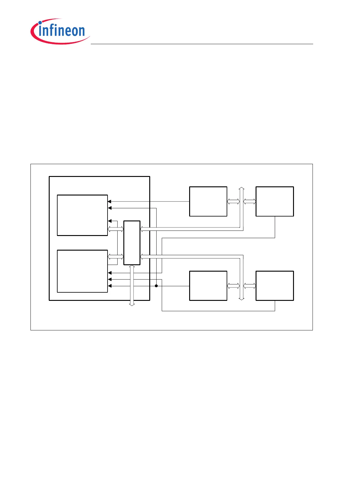
12.1.3 DMA Principles
The DMA controller supports DMA moves from one address location to another one.
DMA moves can be requested either by hardware or by software. DMA hardware
requests are triggered by specific request lines from the peripheral modules or from
other DMA channels (see Figure 12-3). The number of available DMA request lines from
a peripheral module varies depending on the module functionality. Typically, the
occurrence of a receive or transmit data interrupts in a peripheral module are able to
generate a DMA request in parallel to an interrupt request. Therefore, the interrupt
control unit and the DMA controller can react independently to interrupt and DMA
requests that have been generated by one source.
Figure 12-3 DMA Principle
The DMA controller mainly consists of two DMA Sub-Blocks and a Bus Switch. Once
configured, each DMA Sub-Block is able to act as a master on the two FPI Buses.
DMA Controller
MCA05682
FPI Bus 0
Sub-Block 0
Request
Sub-Block 1
Bus Switch
Request
On-Chip
Peripheral
Unit 1
Request
FPI Bus 1
On-Chip
Peripheral
Unit 2
On-Chip
Peripheral
Unit 4
Request
Request
MLI Bus Interface
On-Chip
Peripheral
Unit 3

 Loading...