TC1796
Peripheral Units (Vol. 2 of 2)
Micro Second Channel (MSC)
User’s Manual 21-5 V2.0, 2007-07
MSC, V2.0
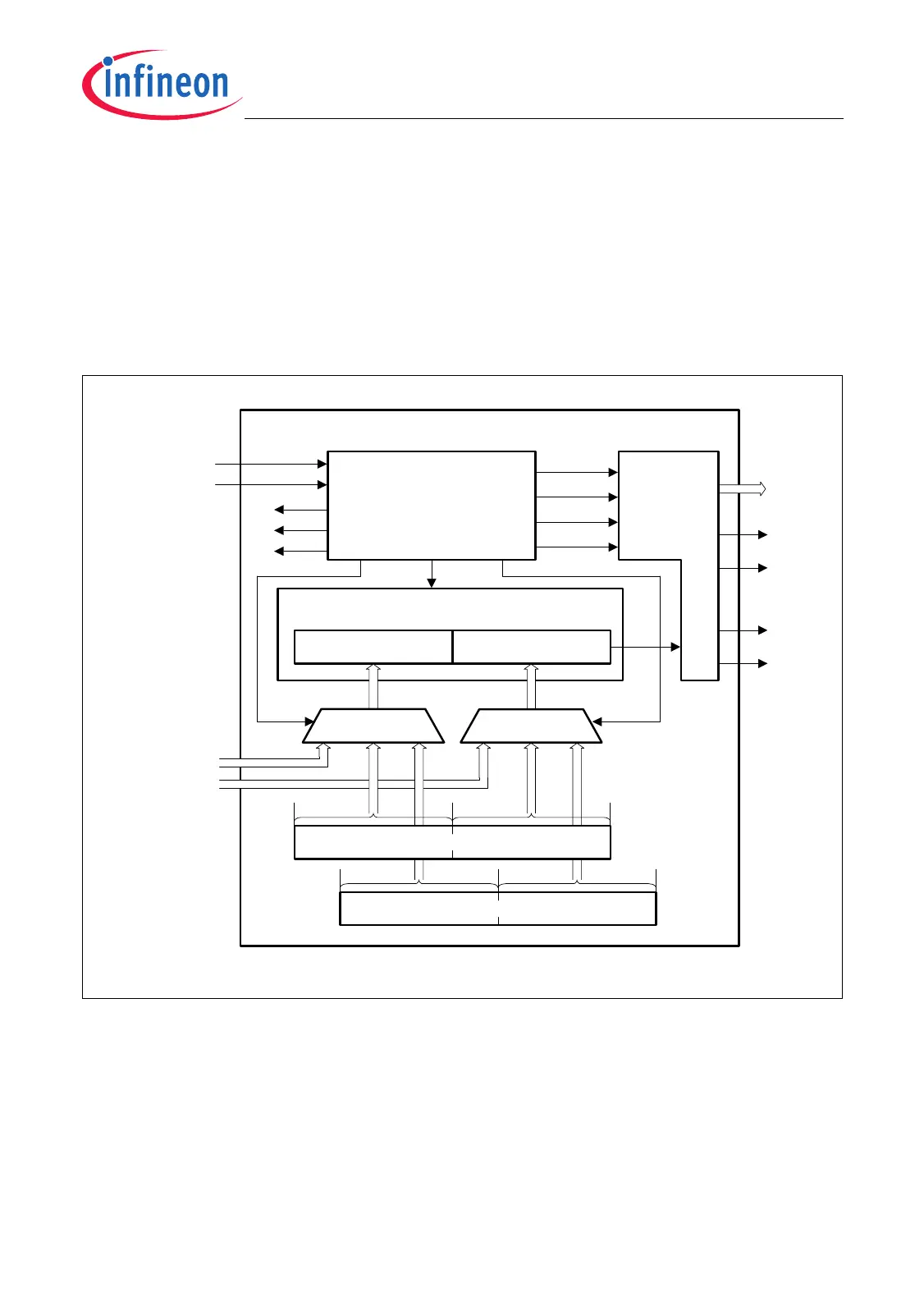
21.1.2 Downstream Channel
The downstream channel performs a high-speed synchronous serial transmission of
data to external devices. Its 32-bit shift register is divided into two 16-bit parts, SRL and
SRH. Each bit of SRL and SRH can be selected to be delivered by the downstream data
register DD, by the Downstream Command Register DC, or by two16-bit wide input
signal buses ALTINL and ALTINH.
Figure 21-3 is a diagram of the MSC downstream channel.
Figure 21-3 Downstream Channel Block Diagram
The enable signals ENL, ENH, and ENC indicate certain phases of the serial
transmission in relation to the serial clock FCL. In the I/O control logic, these signals can
be combined to four enable/select outputs EN[3:0]. For supporting differential output
drivers, the serial clock output FCL and the serial data output SO are available in both
polarities, indicated by the signal name suffix “P” and “N”.
32-Bit Shift Register
SRH (16-Bit) SRL (16-Bit)
MUXMUX
31 1516 0
Downstream
Channel
Control
EDI
ECI
TFI
EN[3:0]
ENL
ENH
SON
SO
FCL
EMGSTOPMSC
ALTINH[15:0]
ALTINL[15:0]
MSC Downstream Channel
f
MSC
MCB05797
Interrupts
Downstream Data Register DD
31 1516 0
Downstream Command Register DC
SOP
FCLN
FCLP
ENC
I/O
Control
 Loading...