TC1796
Peripheral Units (Vol. 2 of 2)
Fast Analog-to-Digital Converter (FADC)
User’s Manual 26-4 V2.0, 2007-07
FADC, V2.0
26.1.1 Analog Inputs
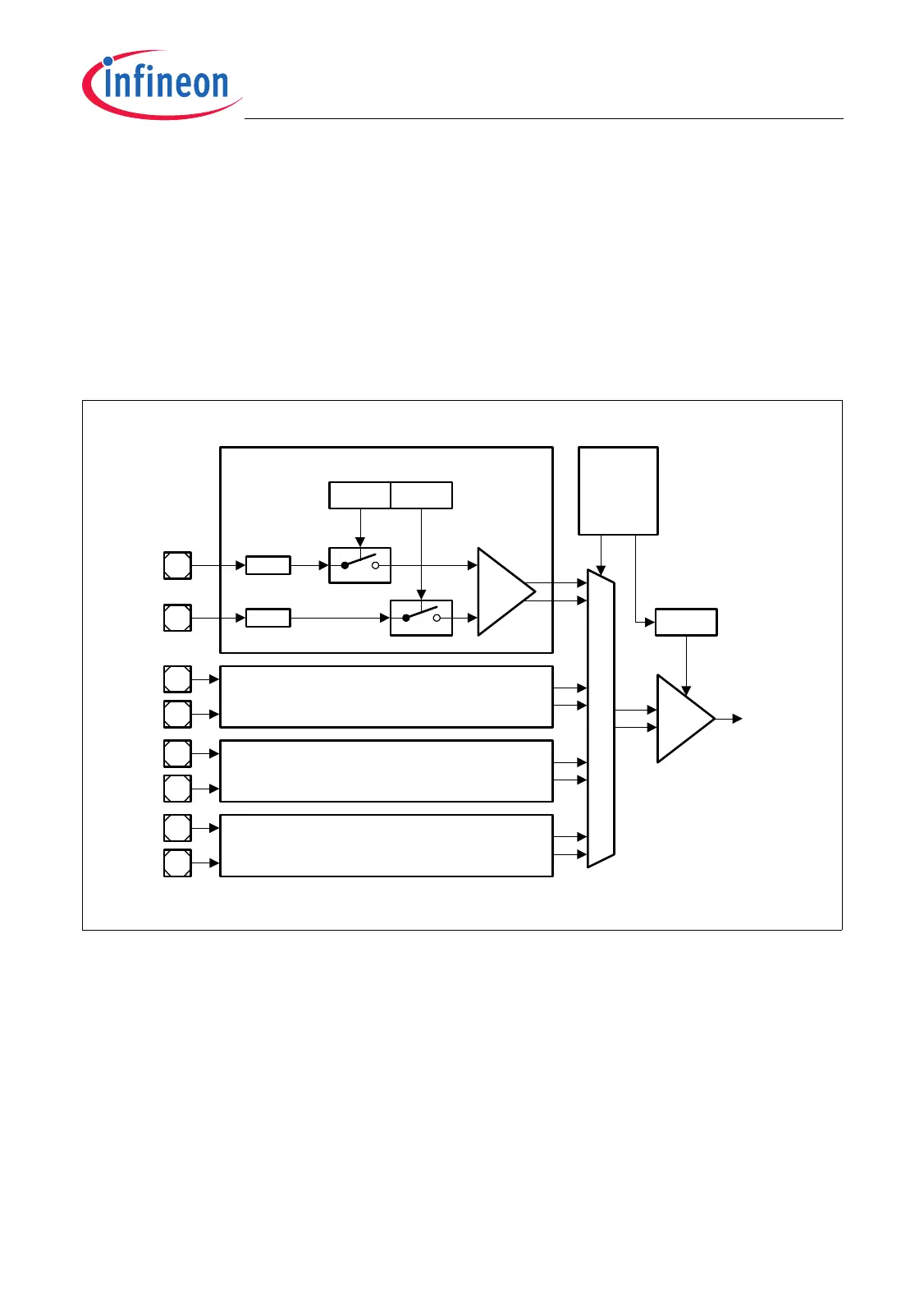
Two analog inputs are assigned to each of the four FADC channels. The FADC analog
input stage contains a differential channel amplifier for each channel and a common
differential amplifier controlling the gain. The two input lines FAINxP/FAINxN (x = 0-3) of
each channel analog input stage can be enabled independently in order to support
single-ended measurements.
The gain of the common amplifier used during an A/D conversion is selected individually
for each of the four channels depending on the currently active channel x.
Figure 26-2 Analog Input Stage
In Multiplexer Test Mode (GCR.MUXTM = 1), the channel amplifiers are disconnected
from the common amplifier. The measured conversion result in multiplexer test mode
should be 10 0000 0000
B
= (200
H
) plus/minus the offset of the common amplifier.
MCA06039
ENP
ACR0
Channel 0
Analog
Input Stage
Rp
Rn
ENN
Channel 1 Analog Input Stage
Channel 2 Analog Input Stage
Channel 3 Analog Input Stage
A/D
Control
GAIN
ACRx
To A/D
Converter
Common
Amplifier
Channel
Amplifier
FAIN0N
FAIN0P
FAIN1N
FAIN1P
FAIN2N
FAIN2P
FAIN3N
FAIN3P

 Loading...