TC1796
Peripheral Units (Vol. 2 of 2)
Analog-to-Digital Converter (ADC)
User’s Manual 25-46 V2.0, 2007-07
ADC, V2.0
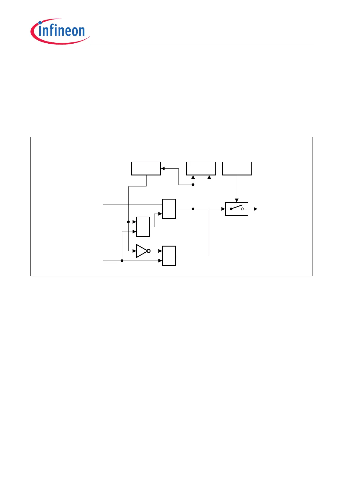
25.1.9.2 Parallel/Serial Request Source Control
The parallel/serial request control logic structure as shown in Figure 25-24 is
almoastidentical with the one shown in Figure 25-23 except that the request input is
controlled by one parallel/serial service request event. As defined in Table 25-9, each of
the four serial/parallel request source (Timer, Queue, Auto-Scan, Synchronized
Injection) has its own request status flag and request enable bit. The service request
flags that are located in register MSS1 can also be set or cleared by software.
Figure 25-24 Parallel/Serial Request Source Logic
MCA06027_mod
Flag
MSS1
Set
Service
Request Event
(Timer, Queue ,
Auto- Scan,
Sync. Injection)
SRTEST
CON
Clear
&
Writing 1 to MSS1 Flag
Clear
&
Flag
SRNP
Parallel /Serial
Service Request
Event
≥1

 Loading...