TC1796
Peripheral Units (Vol. 2 of 2)
Analog-to-Digital Converter (ADC)
User’s Manual 25-108 V2.0, 2007-07
ADC, V2.0
25.3.4 Port Control
The external multiplexer control outputs (and the group select output GRPS for ADC0)
of the ADC modules are controlled in the port logics. For these output lines the following
port control operations must be executed:
• Input/output function selection (IOCR registers)
• Pad driver characteristics selection for outputs (PDR registers)
Input/Output Function Selection
The port input/output control registers contain the bit fields that select the ADC’s digital
I/O driver characteristics such as port direction (input/output), push-pull/open-drain
capabilities, and alternate output selections. The output lines for the ADC modules are
controlled by the port input/output control registers P7_IOCR0 and P7_IOCR4.
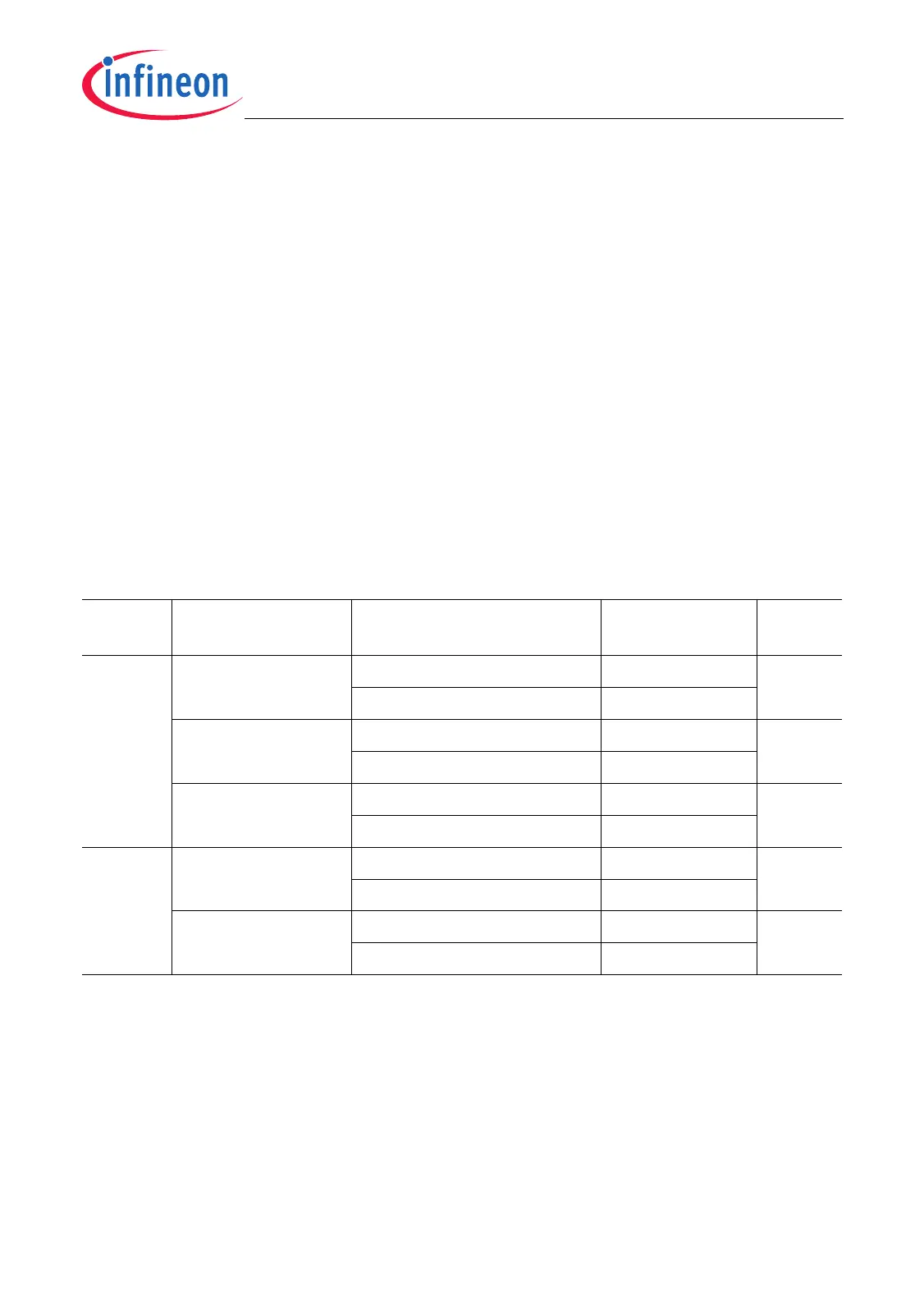
Table 25-14 shows how bits and bit fields must be programmed for the required I/O
functionality of the ADC0/ADC1 I/O lines.
Table 25-14 ADC0/ADC1 I/O Control Selection and Setup
Module Port Lines Input/Output Control
Register Bits
Output
Characteristic
I/O
ADC0 P7.1/AD0EMUX2 P7_IOCR0.PC1 = 1001
B
Push-pull Output
P7_IOCR0.PC1 = 1101
B
Open-drain
P7.2/AD0EMUX0 P7_IOCR0.PC2 = 1001
B
Push-pull Output
P7_IOCR0.PC2 = 1101
B
Open-drain
P7.3/AD0EMUX1 P7_IOCR0.PC3 = 1001
B
Push-pull Output
P7_IOCR0.PC3 = 1101
B
Open-drain
ADC1 P7.6/AD1EMUX0 P7_IOCR4.PC6 = 1001
B
Push-pull Output
P7_IOCR4.PC6 = 1101
B
Open-drain
P7.7/AD1EMUX1 P7_IOCR4.PC7 = 1001
B
Push-pull Output
P7_IOCR4.PC7 = 1101
B
Open-drain

 Loading...