TC1796
System Units (Vol. 1 of 2)
Memory Maps
User’s Manual 9-6 V2.0, 2007-07
MemMaps, V2.0
9.3 Address Map of the FPI Bus System
9.3.1 Segments 0 to 14
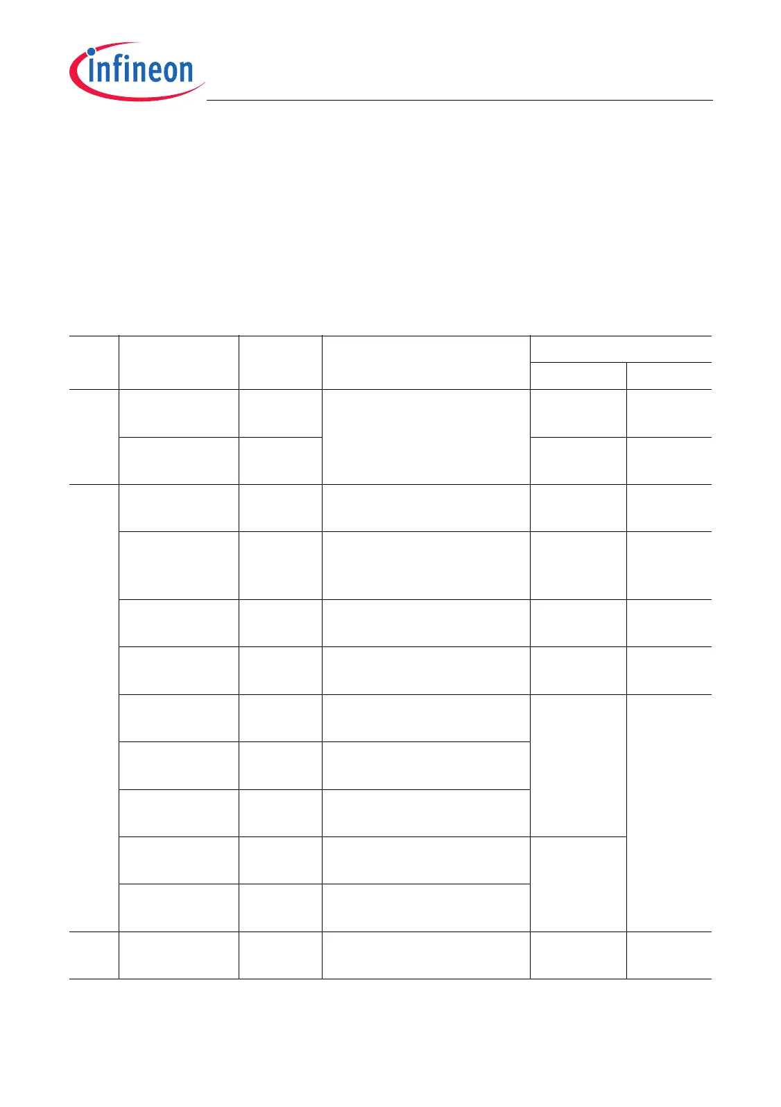
Table 9-2 shows the address map of segments 0 to 14 as it is seen from the SPB and
RPB bus masters PCP, DMA, and OCDS.
Table 9-2 SPB/RPB Address Map of Segment 0 to 14
Seg-
ment
Address
Range
Size Description Access Type
Read Write
0-7 0000 0000
H
-
0000 0007
H
8 byte Reserved (virtual address
space)
MPN trap MPN trap
0000 0008
H
-
7FFF FFFF
H
8 × 256
Mbyte
SPBBE SPBBE
8 8000 0000
H
-
801F FFFF
H
2 Mbyte Program Flash (PFLASH) access access
1)
8020 0000
H
-
807F FFFF
H
6 Mbyte Reserved PLMBBE &
DLMBBE &
SPBBE
PLMBBE
8080 0000
H
-
8FDF FFFF
H
246
Mbyte
External EBU space EBU
access
EBU
access
8FE0 0000
H
-
8FE1 FFFF
H
128
Kbyte
Data Flash (DFLASH) access access
1)
8FE2 0000
H
-
8FEF FFFF
H
896
Kbyte
Reserved PLMBBE &
DLMBBE &
SPBBE
PLMBBE
8FF0 0000
H
-
8FF7 FFFF
H
512
Kbyte
Reserved for TC1796
emulation device memory
8FF8 0000
H
-
8FFF BFFF
H
496
Kbyte
Reserved
8FFF C000
H
-
8FFF DFFF
H
8 Kbyte Boot ROM (BROM) access
8FFF E000
H
-
8FFF FFFF
H
8 Kbyte Test ROM (TROM)
9 9000 0000
H
-
9FFF FFFF
H
256
Mbyte
Reserved SPBBE SPBBE

 Loading...