TC1796
Peripheral Units (Vol. 2 of 2)
Micro Link Interface (MLI)
User’s Manual 23-139 V2.0, 2007-07
MLI, V2.0
23.5.5 On-Chip Connections
23.5.5.1 Service Request Output Connections
Each MLI module provides eight service request outputs SR[7:0] that can be used to
generate interrupts or DMA requests. In the TC1796, four service request outputs
SR[3:0] of the MLI0 module and two service request outputs SR[1:0] of the MLI1 module
are connected to an interrupt node. Service request outputs SR[3:2] of the MLI1 module
are not connected. Four service request outputs (SR[7:4]) of each MLI module are
connected to DMA request inputs of the TC1796 DMA controller.
Each of the service request outputs used as interrupt requests are controlled by a
service request control register. The service request control registers of the MLI modules
are located inside the DMA address area. Therefore, all MLI0/MLI1 service request
control registers are named as DMA_MLIxSRCy and described in the DMA chapter
implementation part (see Page 12-107) of the TC1796 System Units User’s Manual.
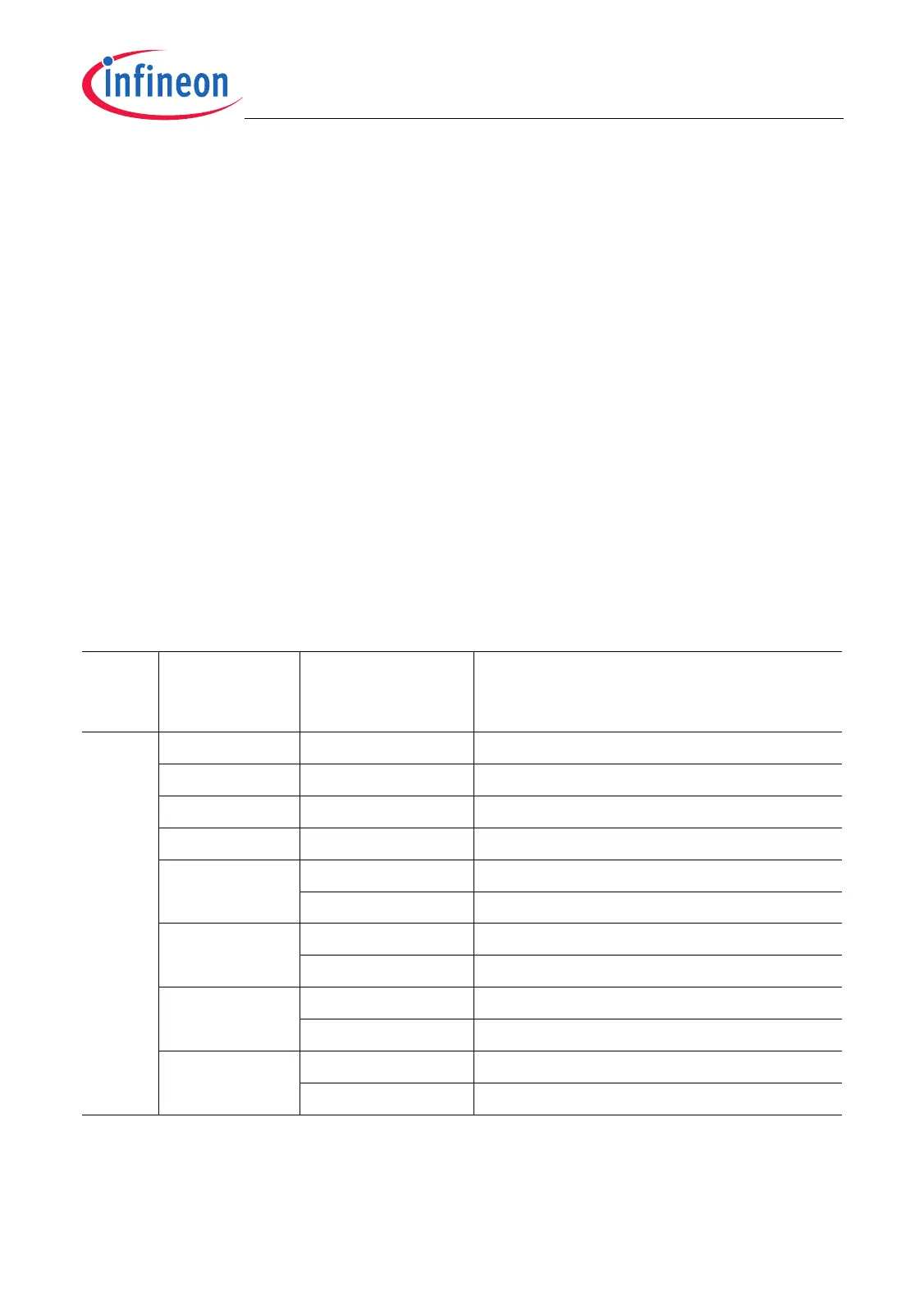
All MLI service request output connections are listed in Table 23-14.
Table 23-14 Service Request Lines and Interconnections of MLI0/MLI1
Module Service Req.
Output Line
Connected to
Node or DMA
Request Input
Description
MLI0 SR0 DMA_MLI0SRC0 MLI0 Service Request Node 0 (in DMA)
SR1 DMA_MLI0SRC1 MLI0 Service Request Node 1 (in DMA)
SR2 DMA_MLI0SRC2 MLI0 Service Request Node 2 (in DMA)
SR3 DMA_MLI0SRC3 MLI0 Service Request Node 3 (in DMA)
SR4 CH00_REQI7 DMA Channel 00 Request Input 7
CH04_REQI7 DMA Channel 04 Request Input 7
SR5 CH01_REQI7 DMA Channel 01 Request Input 7
CH05_REQI7 DMA Channel 05 Request Input 7
SR6 CH02_REQI7 DMA Channel 02 Request Input 7
CH06_REQI7 DMA Channel 06 Request Input 7
SR7 CH03_REQI7 DMA Channel 03 Request Input 7
CH07_REQI7 DMA Channel 07 Request Input 7

 Loading...