TC1796
Peripheral Units (Vol. 2 of 2)
Micro Link Interface (MLI)
User’s Manual 23-138 V2.0, 2007-07
MLI, V2.0
PDx Selection Table
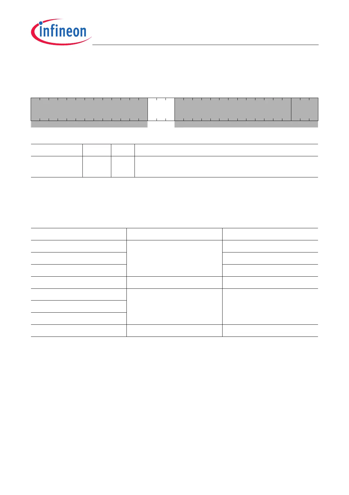
P8_PDR
Port 8 Pad Driver Mode Register (40
H
) Reset Value: 0000 0000
H
31 19 18 16 15 4 3 0
0
PD
MLI1
0 PD0
rrwr rw
Field Bits Type Description
PDMLI1 [18:16] rw Pad Driver Mode for P8.0/TCLK1, P8.2/TVALID1A,
P8.3/TDATA1, and P8.5/RREADY1A
1)
1) Coding of bit field see Table 23-13. Shaded bits and bit fields are “don’t care” for MLI I/O port control.
Table 23-13 Pad Driver Mode Mode Selection (Class A2 Pads)
PDx Bit Field Driver Strength Signal Transitions
000
B
Strong driver Sharp edge
1)
1) In strong driver mode, the output driver characteristics of class A2 pads can be additionally controlled by the
temperature compensation logic.
001
B
Medium edge
1)
010
B
Soft edge
1)
011
B
Weak driver –
100
B
Medium driver –
101
B
110
B
111
B
Weak driver –

 Loading...