TC1796
Peripheral Units (Vol. 2 of 2)
Analog-to-Digital Converter (ADC)
User’s Manual 25-35 V2.0, 2007-07
ADC, V2.0
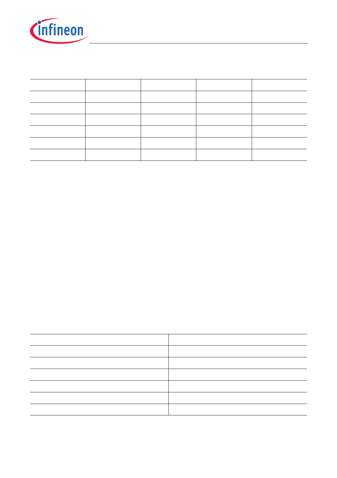
25.1.4.3 Sample Timing Control
The sample time control determines the duration of the sample phase of a conversion,
that is, the period during which the channel input capacitance is charged/discharged by
the selected analog signal source. The duration of the sample phase is programmed
individually for each channel via sample time control bit field CHCONn.STC. Any
modification of CHCONn.STC will be evaluated after the currently performed conversion
is terminated.
The sample time t
S
depends on the basic operating clock f
BC
and the programmable
value of bit field CHCONn.STC. The sample time t
S
is selected in periods of t
BC
=1/f
BC
within the range from 8 × t
BC
up to 1028 × t
BC
.
The sample time t
S
is calculated according to the following equation:
t
S
= 4 × (STC + 2) × t
BC
(25.4)
Table 25-8 shows the selectable values of CON.STC and the resulting ADC basic
operating clock f
BC
and sample time t
S
.
Note: The duration of the sample phase influences the maximum allowable internal
resistance of the respective analog input signal source.
Table 25-7 Conversion Timing Control
CON.CTC f
BC
t
BC
f
ANA
t
ANA
00
H
f
ADC
1 / f
ADC
f
ADC
/ 4 4 / f
ADC
01
H
f
ADC
/ 2 2 / f
ADC ADC
/ 8 8 / f
ADC
02
H
f
ADC
/ 3 3 / f
ADC
f
ADC
/ 12 12 / f
ADC
03
H
f
ADC
/ 4 4 / f
ADC
f
ADC
/ 16 16 / f
ADC
……………
FF
H
f
ADC
/ 256 256 / f
ADC
f
ADC
/ 1024 1024 / f
ADC
Table 25-8 Sample Time Control
CHCONn.STC Sample Time t
S
00
H
8 × t
BC
01
H
12 × t
BC
02
H
16 × t
BC
03
H
20 × t
BC
……
FF
H
1028 × t
BC

 Loading...