TC1796
Peripheral Units (Vol. 2 of 2)
General Purpose Timer Array (GPTA)
User’s Manual 24-24 V2.0, 2007-07
GPTA, V2.0
24.2.2.3 Duty Cycle Measurement Unit (DCM)
The GPTA contains four DCM units (DCM0 to DCM3). The input signal to be analyzed
is delivered as a 2-line signal input (see Figure 24-5 for the event/level input signal
splitting scheme). It is built by:
• An event input, and
• A signal level input.
Each DCM unit has four outputs:
• An event output line,
• An interrupt output that can become active at a signal input rising edge,
• An interrupt output that can become active at a signal input falling edge,
• An interrupt output that can become active at a compare event.
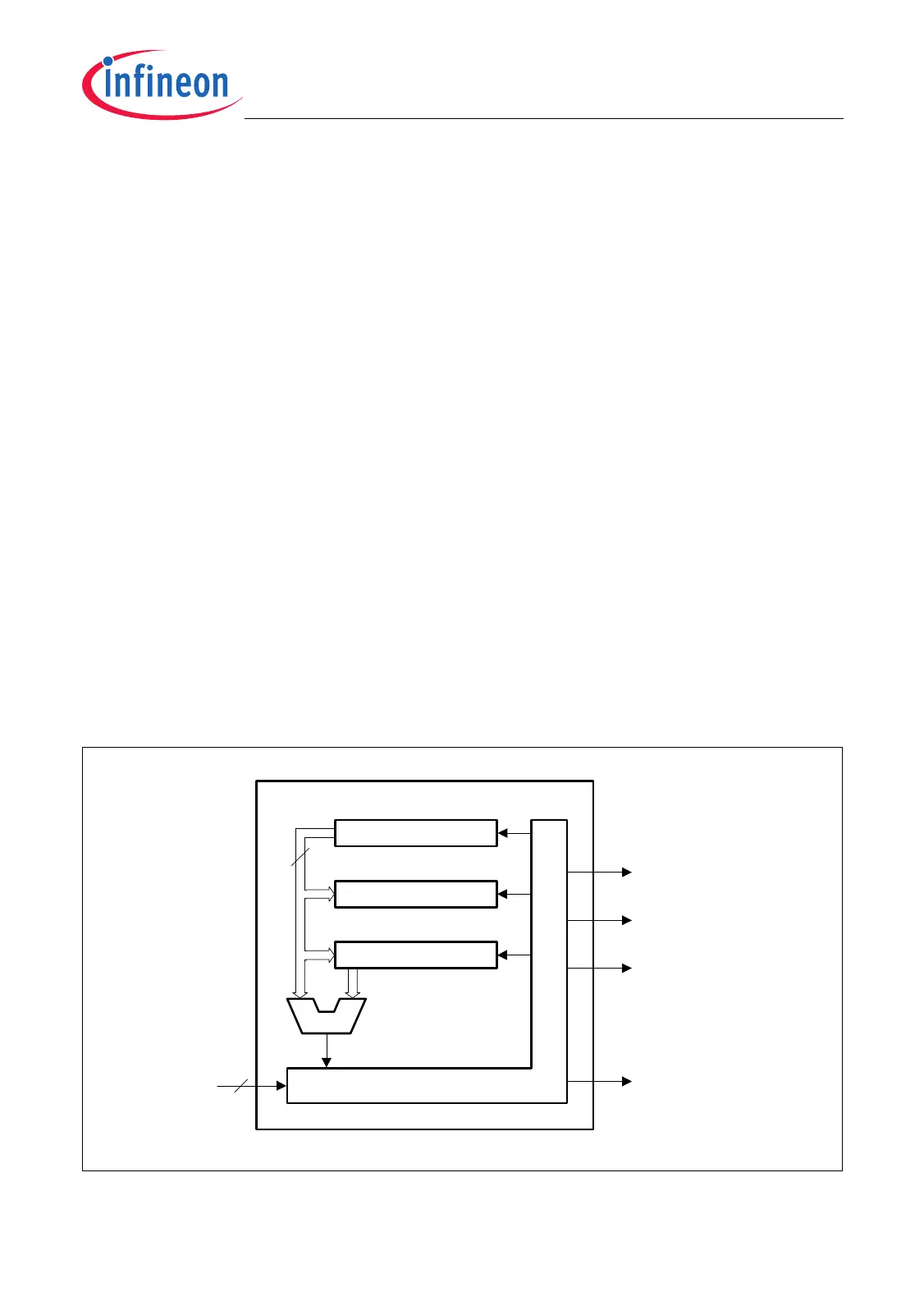
Each DCM unit is equipped with a 24-bit timer, a 24-bit capture register, a 24-bit
capture/compare register, a 24-bit comparator and a DCM control unit (Figure 24-16).
The following registers are assigned to the DCM units:
• DCMCTRk = Duty Cycle Measurement Control Register k (see Page 24-161)
• DCMTIMk = Duty Cycle Measurement Timer Register k (see Page 24-163)
• DCMCAVk = Duty Cycle Measurement Capture Register k (see Page 24-163)
• DCMCOVk = Duty Cycle Measurement Capture/Compare Register k
(also referred as “capcom”, see Page 24-164)
• SRSC0 = Service Request State Clear Register 0 (see Page 24-206)
• SRSS0 = Service Request State Set Register 0 (see Page 24-208)
Figure 24-16 Block Diagram of a Duty Cycle Measurement Unit
MCA05925
24
CE
Rising Edge
Service Request
TIM (Timer)
DCMTIMk
CAV (Capture)
DCMCAVk
COV (Capt./Comp)
DCMCOVk
=
2Signal
Input
DCM Control Unit
Falling Edge
Service Request
Compare
Service Request
Event
Output

 Loading...