TC1796
Peripheral Units (Vol. 2 of 2)
Micro Second Channel (MSC)
User’s Manual 21-15 V2.0, 2007-07
MSC, V2.0
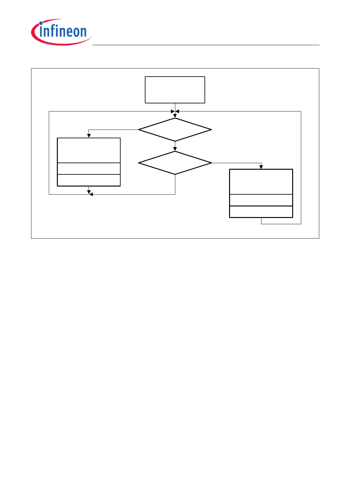
Figure 21-8 Triggered Mode Flow Diagram
Data Repetition Mode
In Data Repetition Mode, data frames are sent out continuously without any software
interaction. In the time gap between two consecutive data frames, passive time frames
can be inserted. The number of passive time frames to be inserted (0 to 15) is defined
by bit field DSS.NPTF. The duration of data frame (t
DF
) and passive time frames (t
PTF
) is
determined by the five data frame parameters (see Equation (21.1)). These parameters
determine time reference points (TRPs) at which a data or passive time frames is started
(see diagram A in Figure 21-9).
The automatic data frame generation is controlled by the data pending bit DSC.DP. This
bit is set near the end of the last transmitted passive time frame. At the next TRP, a data
frame is started (if no command frame has been requested) and DSC.DP is cleared
again by hardware after the data frame has been started. Data Frames are always
aligned to time reference points. This means they always start at a TRP. Passive time
frames can be shortened. This is especially the case when command frames are
inserted.
Continuous data frame transmission can be interrupted by insertion of command frames.
Command frames are initiated by software. When the downstream control register DSC
is written, the command pending bit DSC.CP is set by hardware. CP = 1 indicates that
the MSC starts a command frame at the next TRP, independent of whether a data frame
(indicated by DSC.DP = 1) or passive time frame should be started with the next TRP.
This means that also command frames are always aligned to time reference points.
MCA05802
Starting
Triggered Mode
(writing DSC.TM=0)
DSC.CP = 1?
DSC.DP = 1?
no
yes
Load shift register
for command frame
transmission
Start command frame
DSC.CP = 0
1)
Load shift register
for data frame
transmission
Start data frame
DSC.DP = 0
1)
no
yes
1) Done by hardware.

 Loading...