TC1796
System Units (Vol. 1 of 2)
Direct Memory Access Controller
User’s Manual 12-104 V2.0, 2007-07
DMA, V2.0
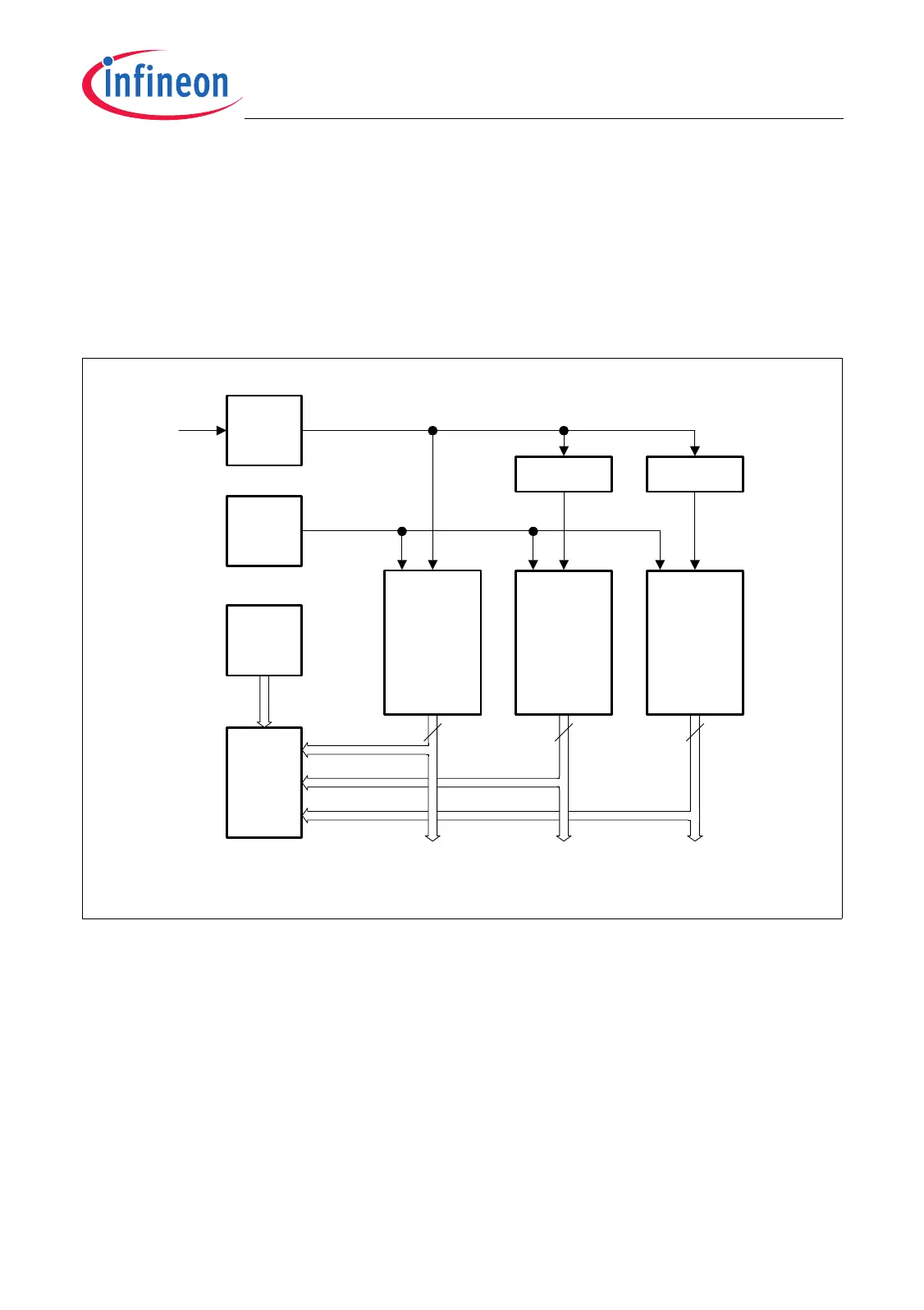
• Eight interrupt requests SR[7:0] = INT_O[7:0] from the DMA controller; upper eight
interrupt requests of the DMA controller INT_O[15:8] are not connected.
• Four interrupt requests SR[3:0] = INT_O[3:0] from the MLI0 module; upper four
interrupt requests of the MLI0 module INT_O[7:4] are not connected.
• Two interrupt requests SR[1:0] = INT_O[1:0] from the MLI1 module; upper six
interrupt requests of the MLI0 module INT_O[7:2] are not connected.
• Four system interrupts SR[3:0] from the SCU.
Figure 12-32 Implementation of the DMA Module and the MLI Modules
DMA
Module
Kernel
Interrupt
Control
in DMA
Module
Clock
Control
Address
Decoder
SR[7:0]
MCA05709
INT_O[15:0]
f
MLI0
f
DMA
MLI0
Module
Kernel
MLI1
Module
Kernel
INT_O[7:0]
INT_O[7:0]
SR[3:0]
SR[1:0]
MLI0_FDR MLI1_FDR
f
MLI1
SR[3:0]
SCU
16 8 8
f
SYS

 Loading...