TC1796
System Units (Vol. 1 of 2)
Introduction
User’s Manual 1-39 V2.0, 2007-07
Intro, V2.0
Parallel Ports
P0
P0.0
P0.1
P0.2
P0.3
P0.4
P0.5
P0.6
P0.7
P0.8
P0.9
P0.10
P0.11
P0.12
P0.13
P0.14
P0.15
A9
A8
A7
B8
B7
A6
B6
C8
C7
B5
C6
D6
C5
D5
A5
D4
I/O
I/O
I/O
I/O
I/O
I/O
I/O
I/O
I/O
I/O
I/O
I/O
I/O
I/O
I/O
I/O
I/O
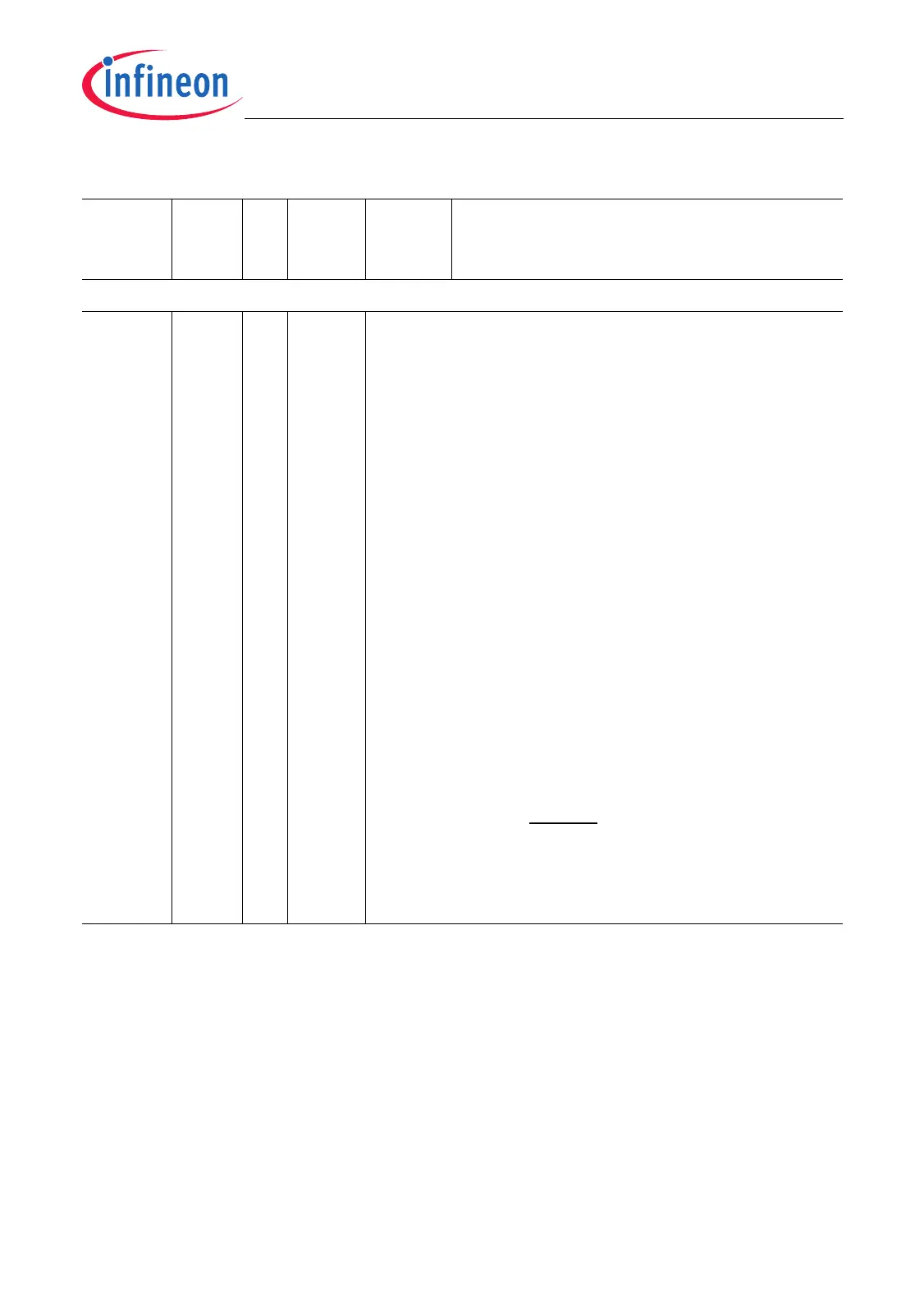
A1 Port 0
Port 0 is a 16-bit bi-directional general-purpose I/O
port.
Port 0 I/O line 0
Port 0 I/O line 1
Port 0 I/O line 2
Port 0 I/O line 3
Port 0 I/O line 4
Port 0 I/O line 5
Port 0 I/O line 6
Port 0 I/O line 7
Port 0 I/O line 8
Port 0 I/O line 9
Port 0 I/O line 10
Port 0 I/O line 11
Port 0 I/O line 12
Port 0 I/O line 13
Port 0 I/O line 14
Port 0 I/O line 15
The states of the Port 0 pins are latched into the
software configuration input register SCU_SCLIR at
the rising edge of HDRST.
In the different TC1796 device versions several Port 0
pins are reserved for device configuration purposes
(see Page 10-25).
Table 1-3 Pin Definitions and Functions (cont’d)
Symbol Pins I/O Pad
Driver
Class
Power
Supply
Functions

 Loading...