TC1796
System Units (Vol. 1 of 2)
Interrupt System
User’s Manual 14-16 V2.0, 2007-07
Interrupt, V2.0
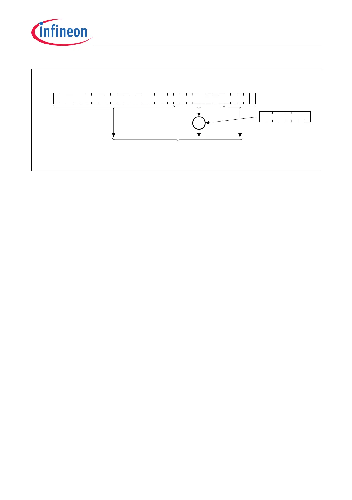
Figure 14-2 Interrupt Vector Table Entry Address Calculation
Left-shifting the PIPN by 5 bits creates entries into the Interrupt Vector Table which are
evenly spaced 8 words apart. If an ISR is very short, it may fit entirely within the eight
words available in the vector table entry. Otherwise, the code at the entry point must
ultimately cause a jump to the rest of the ISR residing elsewhere in memory. Due to the
way the vector table is organized according to the interrupt priorities, the TC1796 offers
an additional option by allowing spanning several Interrupt Vector Table entries so long
as those entries are otherwise unused. Figure 14-3 illustrates this.
The required size of the Interrupt Vector Table depends only on the range of priority
numbers actually used in a system. Of the 256 vector entries, 255 may be used. Vector
entry 0 is never used, because if ICR.PIPN is 0, the CPU is not interrupted. Distinct
interrupt handlers are supported, but systems requiring fewer entries need not dedicate
the full memory area required by the largest configurations.
MCA05743
0
0000
531
BIV
PIPN
OR
Resulting Interrupt Vector Table Entry Address
00
12
000

 Loading...