TC1796
Peripheral Units (Vol. 2 of 2)
Synchronous Serial Interface (SSC)
User’s Manual 20-32 V2.0, 2007-07
SSC, V2.1
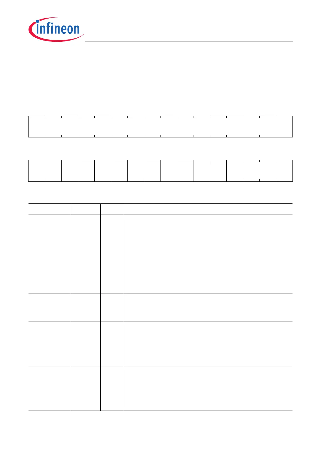
The operating modes of the SSC are controlled by the Control Register CON. This
register contains control bits for mode and error check selection.
CON
Control Register (10
H
) Reset Value: 0000 0000
H
31 30 29 28 27 26 25 24 23 22 21 20 19 18 17 16
0
r
1514131211109876543210
EN MS 0
A
REN
BEN PEN REN TEN LB PO PH HB BM
rwrw r rwrwrwrwrwrwrwrwrw rw
Field Bits Type Description
BM [3:0] rw Data Width Selection
BM determines the number of data bits of the serial
frame.
0000
B
Reserved; do not use this combination.
0001
B
Transfer Data Width is 2 bit.
0010
B
Transfer Data Width is 3 bit.
…
B
…
1110
B
Transfer Data Width is 15 bit.
1111
B
Transfer Data Width is 16 bit.
HB 4rwHeading Bit Control
0
B
Transmit/Receive LSB First
1
B
Transmit/Receive MSB First
PH 5rwClock Phase Control
0
B
Shift transmit data on the leading clock edge,
latch on trailing edge
1
B
Latch receive data on leading clock edge, shift
on trailing edge
PO 6rwClock Polarity Control
0
B
Idle clock line is low, the leading clock edge is
low-to-high transition
1
B
Idle clock line is high, the leading clock edge is
high-to-low transition

 Loading...