TC1796
Peripheral Units (Vol. 2 of 2)
Micro Second Channel (MSC)
User’s Manual 21-17 V2.0, 2007-07
MSC, V2.0
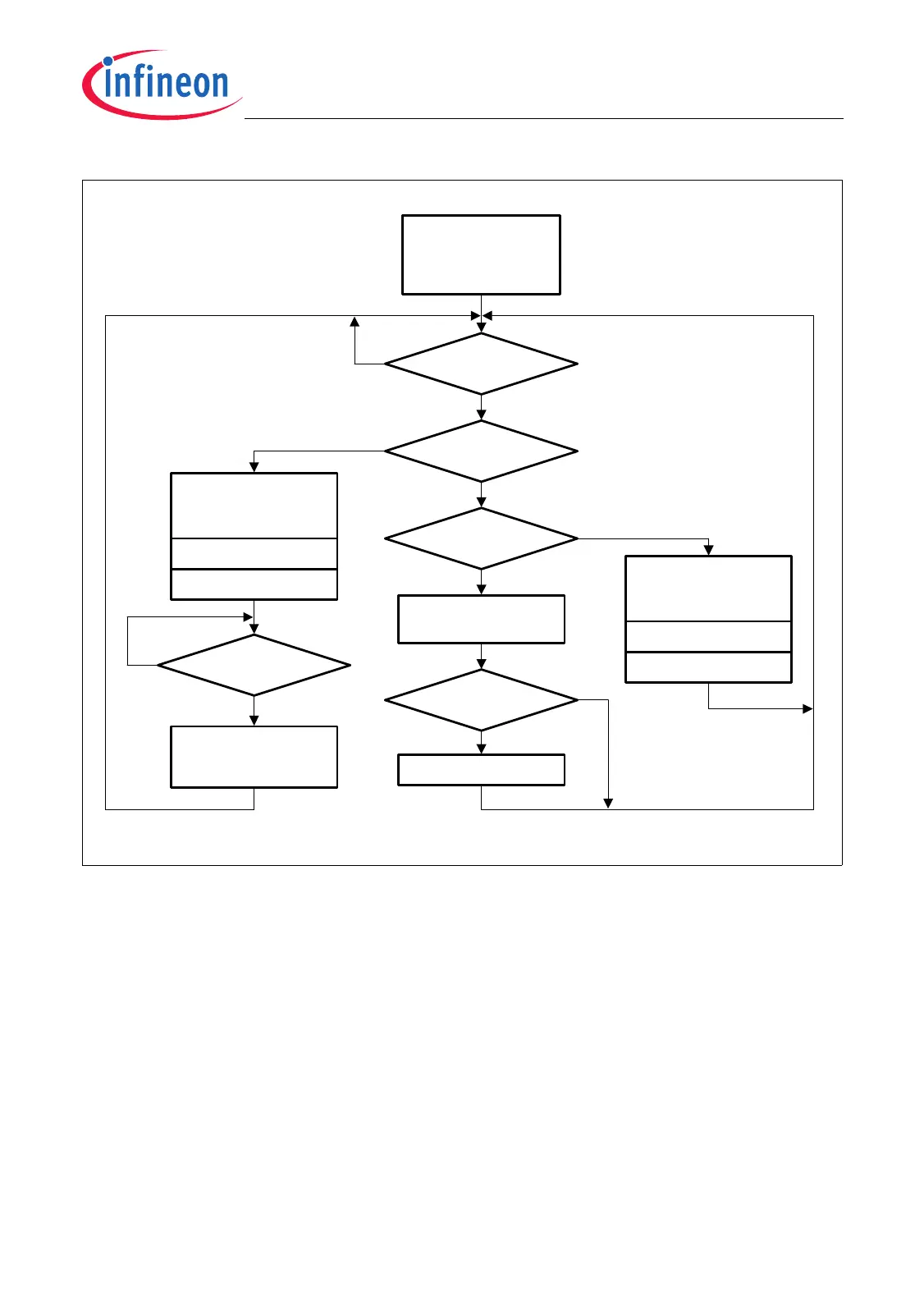
Figure 21-10 Data Repetition Mode Flow Diagram
The type of the active frame (data or command frame) that is currently processed and
output is indicated by two status flags: DSS.DFA is set during a data frame transmission
and DSS.CFA is set during a command frame transmission. Further, the downstream
counter DSS.DC indicates the number of shift clock periods that have been elapsed
since the start of the current data, command, or passive time frame.
As in Triggered Mode, the shift register loading event described in Section 21.1.2.2
occurs in Data Repetition Mode just before a TRP, i.e. shortly before a command or data
frame transmission is started.
MCA05804
Starting Data
Repetition Mode
(writing DSC.TM=1)
DSC.CP = 1?
yes
no
TRP reached?
DSC.DP = 1?
Start passive
time frame
no
yes
Load shift register
for command frame
transmission
Start command frame
Cmd. frame
finished?
no
DSC.CP = 0
1)
Load shift register
for data frame
transmission
Start data frame
DSC.DP = 0
1)
Last Passive
Time Frame?
no
DSC.DP = 1
1)
yes
yes
no
yes
Start shortened
passive time frame
1) Done by hardware
 Loading...