TC1796
Peripheral Units (Vol. 2 of 2)
Micro Link Interface (MLI)
User’s Manual 23-35 V2.0, 2007-07
MLI, V2.0
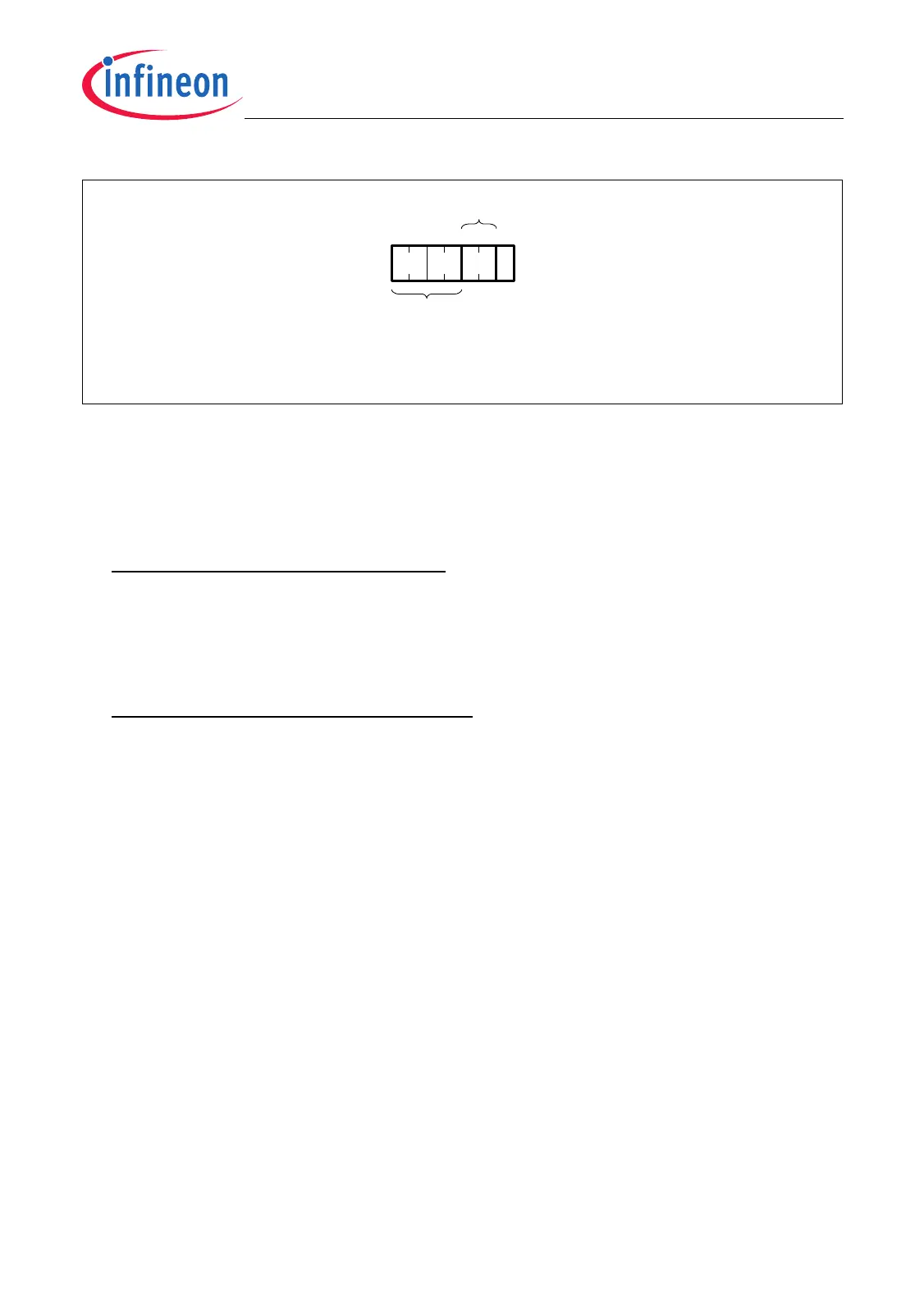
Figure 23-28 Optimized Read Frame
Remote Controller
After a Read Frame has been correctly received and acknowledged, the following
actions are executed in the MLI receiver of the Remote Controller:
• In the case of a Discrete Read Frame:
The result of the address prediction is not taken into account. The received offset
address is added to the base address of the pipe x Transfer Window (stored in
RPxBAR.ADDR). The result of this addition is stored in RADRR.ADDR and also in
RPxBAR.ADDR and represents the destination address in the Remote Controller
from where data should be read.
In the case of an Optimized Read Frame:
The result of the address prediction is taken into account. The next address in the
Remote Controller where data should be read is calculated by adding the detected
receiver address prediction value RPxSTATR.AP to the actual address stored in
RPxBAR.ADDR. The result of this addition is stored in RADRR.ADDR and also in
RPxBAR.ADDR and represents the destination address in the Remote Controller
from where data should be read.
• The transmitted data width DW is written into bit field RCR.DW.
• The information about the received frame type (= 01
B
for a Read Frame) is written
into bit field RCR.TF.
• MLI event status flag RISR.NFRI (Normal Frame Received event) is set and a service
request output is activated if enabled by RIER.NFRIE = 01
B
or 10
B
.
After correct reception of a Read Frame by the Remote Controller, the data requested
by the Local Controller can be read by the Remote Controller and sent back to the Local
Controller in form of an Answer Frame.
This read operation can be executed in two ways:
• RCR.MOD = 0:
Automatic Data Mode is disabled. In this mode, a bus master of the Remote
Controller, typically a CPU, is informed by a Normal Frame received event to read the
requested read data and transfer it to the MLI receiver. Therefore, it must read data
MCA05885
x
P
Header
1 DW
TPxSTATR.DW
1
DW = Data Width
x = Pipe Number
0246315
 Loading...