TC1796
Peripheral Units (Vol. 2 of 2)
Micro Link Interface (MLI)
User’s Manual 23-34 V2.0, 2007-07
MLI, V2.0
Local Controller
A read operation from a location within a Transfer Window x of the Local Controller
delivers a dummy value as result of the read action and triggers the transmission of a
Read Frame. The dummy value of the initial read action should be ignored and the
software has to wait for the reception of the Answer Frame to get the desired data.
• The 16 least significant address bits of the Transfer Window read access are stored
in TPxAOFR.AOFF as read offset address. In case of a an access to a Small Transfer
Window, also 16 bits are stored, but the higher bits are not taken into account.
• The data width of the Transfer Window read access (8-bit, 16-bit, or 32-bit) is stored
in bit field TPxSTATR.DW.
• Status flag TRSTATR.DVx (data valid) is set.
• Status flag TRSTATR.RPx (read pending) is set. This bit is cleared by hardware
when an Answer Frame has been received correctly.
• If the address prediction method is not enabled (TCR.NO = 1), transmission of a
Discrete Read Frame is started. If the address prediction method is enabled
(TCR.NO = 0), a Discrete Read Frame is started only if an address prediction is not
possible (indicated by TPxSTATR.OP = 0). If TPxSTATR.OP = 1, an address
prediction is possible and an Optimized Read Frame is started.
• Status flag TRSTATR.DVx is cleared by hardware and MLI event status flag
TISR.NFSIx (Normal Frame Sent event in pipe x) is set (and a service request output
is activated if enabled by TIER.NFSIEx = 1) after the Read Frame has been finished
and correctly acknowledged by the MLI receiver of the Remote Controller.
The number m of offset address bits that are transmitted at a Discrete Read Frame is
determined by the (coded) size of the Remote Window in the Remote Controller that has
been previously initialized by the transmission of a Copy Base Address Frame.
Parameter m is stored in bit field TPxSTATR.BS (and RPxSTATR.BS) and can be in the
range of 1 to 16 bits.
After a completed transmission of a Read Frame, the Local Controller expects the
reception of an Answer Frame. The Answer Frame is introduced with the highest priority
into the data flow of the transmitter of the Remote Controller.
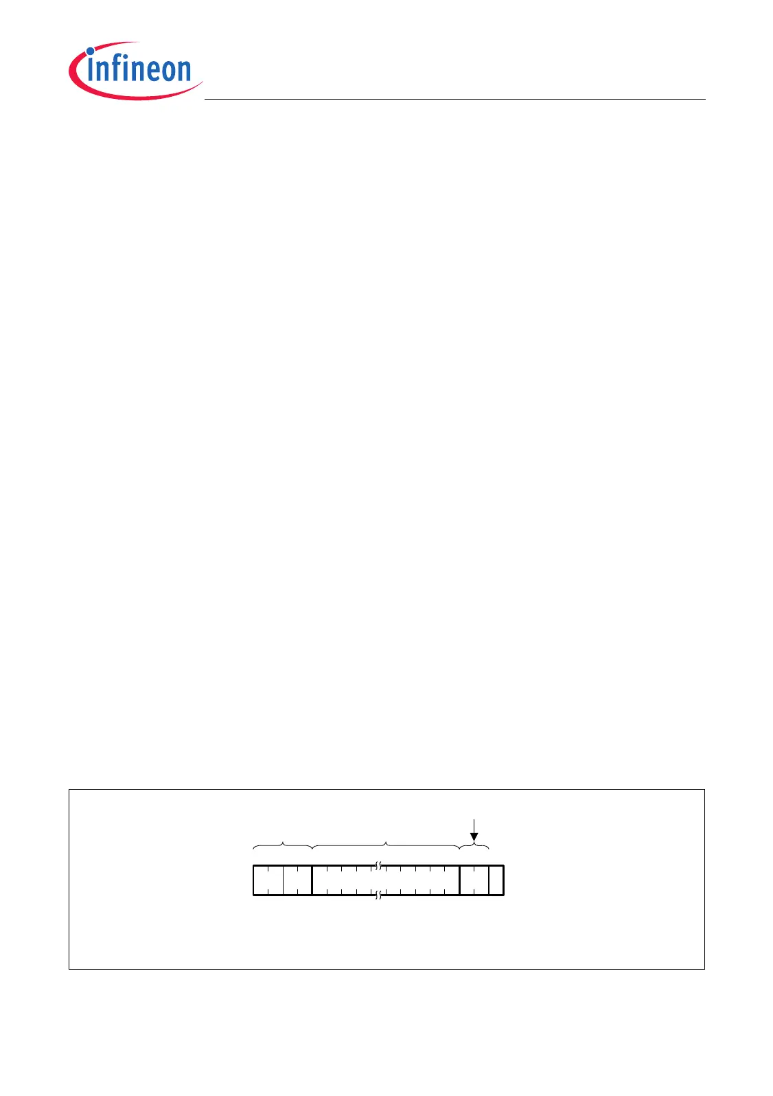
Figure 23-27 Discrete Read Frame
MCA05881
x
P
DW01 m-Bit Offset Address
m = TPxSTATR.BS
x = Pipe Number
DW = Data Width
02 6+m314
TPxSTATR.DW
TPxAOFR.AOFFHeader
 Loading...