TC1796
Peripheral Units (Vol. 2 of 2)
Micro Link Interface (MLI)
User’s Manual 23-126 V2.0, 2007-07
MLI, V2.0
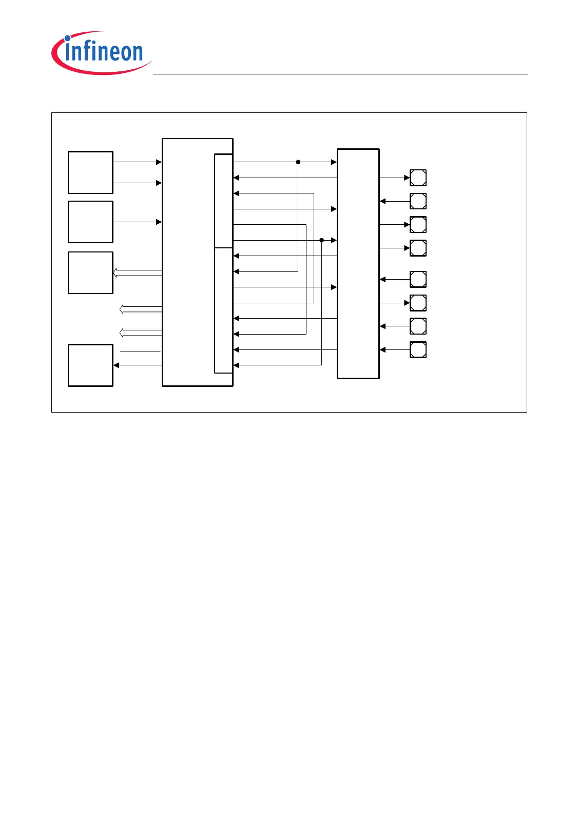
Figure 23-52 MLI1 Module Implementation and Interconnections
When programming the MLI1_OICR register, the following additional items must be
considered:
• Lines with index “B” (not shown in the figure above)
– Unused transmitter/receiver output lines TVALIDB and RREADYB are not
connected.
– Unused transmitter/receiver input lines TREADYB, RCLKB, RVALIDB, and
RDATAB are connected to low level.
• Lines with index “C” (not shown in the figure above)
– Unused transmitter/receiver output lines TVALIDC and RREADYC are reserved
for emulation purposes.
– Unused transmitter/receiver input lines TREADYC, RCLKC, RVALIDC, and
RDATAC are reserved for emulation purposes and should not be selected during
normal operation of the TC1796.
See also Page 23-130 for additional details on I/O line control and function.
Interrupt
Control
MCA05907
Port 8
Control
SR[1:0]
f
MLI1
Address
Decoder
Clock
Control
Not
Connected
TREADYA
MLI1
Module
(Kernel)
TCLK
SR[3:2]
TREADYD
TVALIDA
TVALIDD
TDATA
TransmitterReceiver
RCLKA
RCLKD
RREADYA
RREADYD
RVALIDA
RVALIDD
RDATAA
RDATAD
To DMA
SR[7:4]
BRKOUT
P8.0 / TCLK1
P8.1 / TREADY1A
P8.2 / TVALID1A
P8.3 / TDATA1
P8.4 / RCLK1A
P8.5 / RREADY1A
P8.6 / RVALID1A
P8.7 / RDATA1A
f
DMA
Cerberus
A2
A2
A2
A1
A1
A1
A2
A1

 Loading...