TC1796
System Units (Vol. 1 of 2)
Clock System and Control
User’s Manual 3-33 V2.0, 2007-07
Clock, V2.0
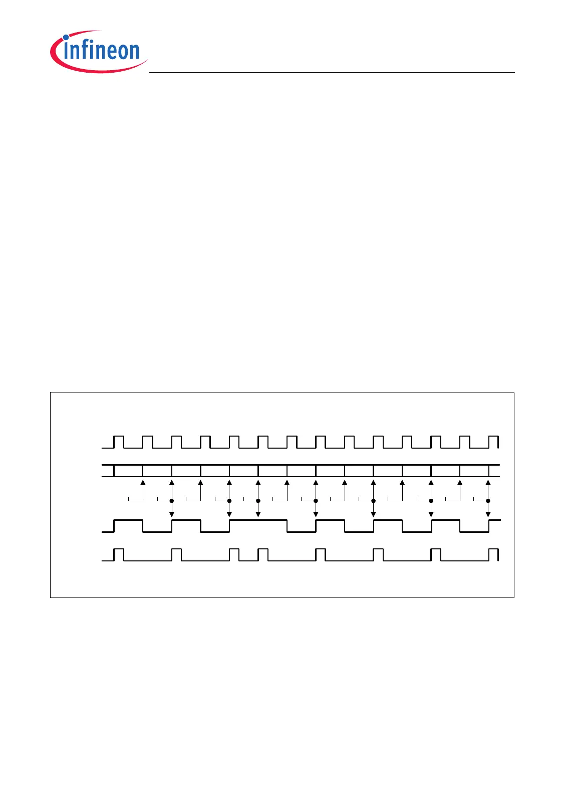
Fractional Divider Mode
When the fractional divider mode is selected (FDR.DM = 10
B
), the output clock f
OUT
is
derived from the input clock f
IN
by division of a fraction of n/1024 for any value of n from
0 to 1023. In general, the fractional divider mode makes it possible to program the
average output clock frequency with a higher accuracy than in normal divider mode.
In fractional divider mode, an output clock pulse at f
OUT
is generated depending on the
result of the addition FDR.RESULT + FDR.STEP. If the addition leads to an overflow
over 3FF
H
, a pulse is generated at f
OUT
. Note that in fractional divider mode the clock f
OUT
can have a maximum period jitter of one f
IN
clock period.
The output frequencies in fractional divider mode are defined according to the following
formulas:
, with n = 0-1023 (3.6)
Figure 3-8 shows the operation of the fractional divider mode with a reload value of
FDR.STEP = 234
H
(= factor 564/1024 = 0.55). The clock signal f
OUT
is the AND
combination of the f
OUT
Enable signal with f
IN
.
Figure 3-8 Fractional Divider Mode Timing
f
OUT
f
IN
n
1024
-------------
×=
RESULT 150
f
IN
STEP = 234
H
: f
OUT
= 0.55 x f
IN
f
OUT
Enable
384 1B8
+234
3EC 220 054 288 0BC 2F0 124 358 18C
+234
+234 +234 +234 +234 +234 +234 +234
3C0
+234
+234 +234 +234
MCT05606
f
OUT

 Loading...