TC1796
System Units (Vol. 1 of 2)
System Control Unit
User’s Manual 5-17 V2.0, 2007-07
SCU, V2.0
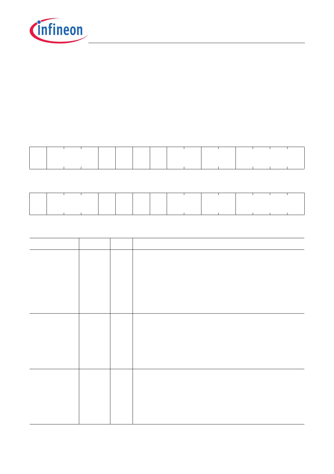
The External Input Channel Register EICR0 and EICR1 for the external input channels
0 to 3 contain bits to configure the input gating logic IGL and the event trigger logic ETL.
A maximum of 12 input channels are supported by one input unit (defined by the
maximum number of IGCRy.IPENx bits).
EICR0
External Input Channel Register 0
(F0000080
H
) Reset Value: 0000 0000
H
31 30 29 28 27 26 25 24 23 22 21 20 19 18 17 16
0INP1
EI
EN1
LD
EN1
R
EN1
F
EN1
0EXIS1 0
r rw rwrwrwrw r rw r
1514131211109876543210
0INP0
EI
EN0
LD
EN0
R
EN0
F
EN0
0EXIS0 0
r rw rwrwrwrw r rw r
Field Bits Type Description
EXIS0 [5:4] rw External Input Selection 0
This bit field determines which input line is selected
for signal IN0.
00
B
Input IN00 is selected.
01
B
Input IN01 is selected.
10
B
Input IN02 is selected.
11
B
Input IN03 is selected.
FEN0 8rwFalling Edge Enable 0
This bit determines if the falling edge of signal IN0 is
used to set bit INTF0.
0
B
The falling edge is not used.
1
B
The detection of a falling edge of IN0 generates
a trigger event (INTF0 becomes set).
REN0 9rwRising Edge Enable 0
This bit determines if the rising edge of signal IN0 is
used to set bit INTF0.
0
B
The rising edge is not used.
1
B
The detection of a rising edge of IN0 generates
a trigger event (INTF0 becomes set).

 Loading...