TC1796
System Units (Vol. 1 of 2)
System Control Unit
User’s Manual 5-32 V2.0, 2007-07
SCU, V2.0
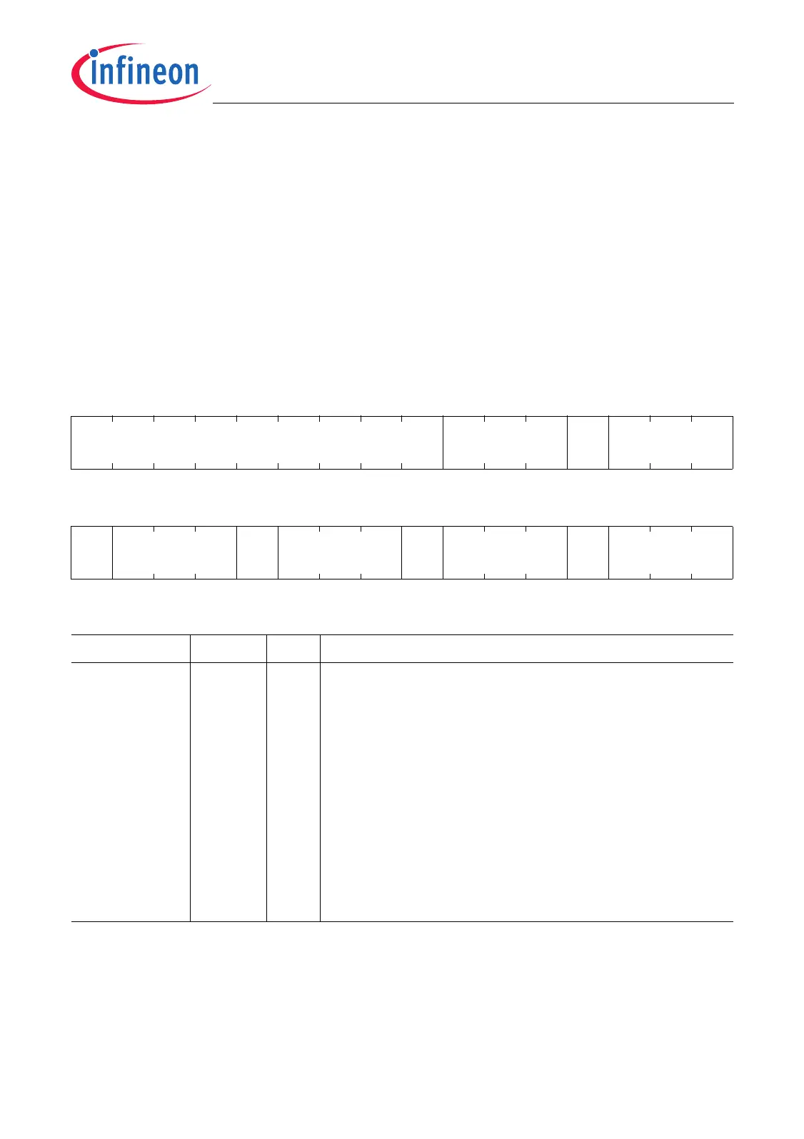
The Trigger Gating ADC0 Register TGADC0 contains bit fields that determine the
assignment of the output signals of the external request unit to the trigger and gating
inputs of ADC0. The Trigger Gating ADC1 Register TGADC1 contains bit fields that
determine the assignment of the output signals of the external request unit to the trigger
and gating inputs of ADC1. Suffix “x” (x = 0,1) in the bit descriptions refers to the
corresponding A/D converter, ADC0 or ADC1.
TGADC0
Trigger Gating ADC0 Register (F000009C
H
) Reset Value: 0000 0000
H
TGADC1
Trigger Gating ADC1 Register (F00000A0
H
) Reset Value: 0000 0000
H
31 30 29 28 27 26 25 24 23 22 21 20 19 18 17 16
0 SW0GTSEL 0 EGTSEL
rrwrrw
1514131211109876543210
0 TTRSEL 0 QTRSEL 0 SW0TRSEL 0 ETRSEL
rrwrrwrrwrrw
Field Bits Type Description
ETRSEL [2:0] rw External Trigger Request Selection
This bit determines which trigger source will be used
for the external trigger request input ETR of ADCx.
000
B
ETR is constant at 0 level (trigger function
switched off).
001
B
ROUT0 is connected to ETR.
010
B
ROUT1 is connected to ETR.
011
B
ROUT2 is connected to ETR.
100
B
TOUT0 is connected to ETR.
101
B
TOUT1 is connected to ETR.
110
B
TOUT2 is connected to ETR.
111
B
TOUT3 is connected to ETR.

 Loading...