TC1796
System Units (Vol. 1 of 2)
System Control Unit
User’s Manual 5-65 V2.0, 2007-07
SCU, V2.0
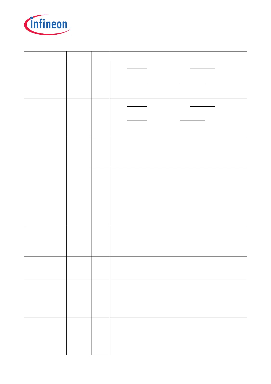
CSOEN 2rwCSOVL Enable
0
B
CSOVL will not activate CSCOMB
(default after reset)
1
B
CSOVL will activate CSCOMB
See also Figure 13-10 on Page 13-29.
CSGEN 3rwCSGLB Enable
0
B
CSGLB will not activate CSCOMB
(default after reset).
1
B
CSGLB will activate CSCOMB.
See also Figure 13-10 on Page 13-29.
EPUD 4rwEBU Pull-up Disable
0
B
Pull-up resistors are enabled
(default after reset).
1
B
Pull-up resistors are disabled.
NMIEN 5rwsNMI Enable
0
B
NMI is disabled (default).
1
B
NMI is enabled.
This bit is cleared with any reset.
It can be only set by software and will remain in this
state until the next reset. Writing a zero to this bit has
no effect. The NMI is described in detail at
Section 14.10 on Page 14-25.
AN7TM 6rwAnalog Input 7 Test Mode
0
B
Pull down of analog input 7 is disabled (default
after reset).
1
B
Pull down of analog input 7 is enabled.
DTSON 9rwDie Temperature Sensor On
0
B
Die temperature sensor is switched off.
1
B
Die temperature sensor is switched on.
LDEN 10 rw LVDS Driver Enable
0
B
The LVDS drivers are disabled and in power-
down mode.
1
B
The LVDS drivers are enabled.
See also Page 10-85.
RPARAV 11 rw Reset SRAM Parity Available Bit
0
B
No action
1
B
Clear bit SCU_STAT.PARAV
This bit is always read as 0.
See also “SRAM Parity Control” on Page 5-37.
Field Bits Type Description
 Loading...