TC1796
System Units (Vol. 1 of 2)
On-Chip System Buses and Bus Bridges
User’s Manual 6-20 V2.0, 2007-07
Buses, V2.0
When an FPI Bus master attempts to initiate a transfer on the FPI Bus, it first signals a
request for bus ownership to the bus control unit. When bus ownership is granted by the
bus control unit, an FPI Bus read or write transaction is initiated. The unit targeted by the
transaction becomes the FPI Bus slave, and responds with the requested action.
Some functional units operate only as slaves, while others can operate as either masters
or slaves. In the TC1796, DMI and PMI (via the LFI Bridge), PCP, DMA, and Cerberus
operate as FPI Bus masters. On-chip peripheral units are typically FPI Bus slaves.
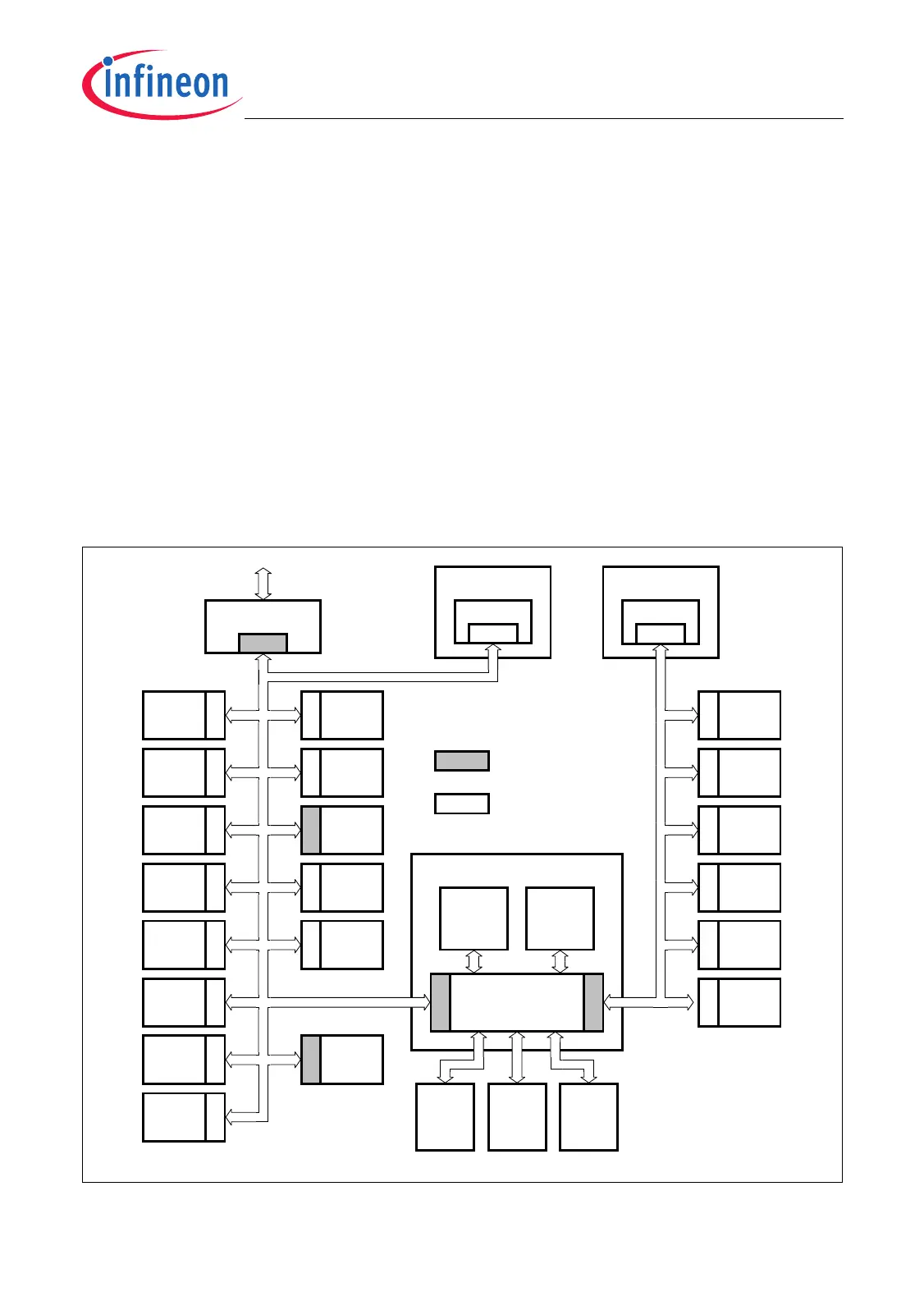
Figure 6-6 shows the two FPI Buses and the interface types of the various modules.
FPI Bus arbitration is performed by the Bus Control Unit (BCU) of the FPI Bus. In case
of bus errors, the BCU generates an interrupt request to the CPU and provides
debugging information about the actual bus error to the CPU.
In the TC1796, device external memory/peripheral accesses are handled via the EBU as
part of the PMU. Therefore, the FPI Buses are not required for such type of device
external transactions.
Figure 6-6 TC1796 FPI Buses Block Diagram
SlaveSlaveSl a v eSlaveSlave Slave
SlaveSl a v eSlave Slave
DMI
PCP2
DMA Controller
MCB05632_mod
System Peripheral Bus
Remote Peripheral Bus
LFI Bridge
M/S
M/S
SBCU
STM
Ports
SCU
ASC0
ASC1
SSC0
SSC1
GPTA0
Slave
GPTA1
LTCA2
SlaveSlave
MSC0
MSC1
Slave
CAN
ADC0
ADC1
FADC
RBCU
MLI0 MLI1
MEM
CHK
Bus Switch
M/S
M/S
Move
Engine
0
Move
Engine
1
Slave Sl av eSlaveSl av e
Data Local
Memory Bus
DPRAM
Slave
TriCore CPU
CPS
Slave
M/S
Slave
Master/Slave
FPI Bus Interface
Slave
FPI Bus Interface
M/S
OCDS

 Loading...