TC1796
System Units (Vol. 1 of 2)
On-Chip System Buses and Bus Bridges
User’s Manual 6-54 V2.0, 2007-07
Buses, V2.0
CHNR0y
(y = 0-7)
16 + y rh DMA Channel Number Status
These bits indicate which DMA channel with number
1y was active when a DMA break trigger event
occurred at the RPB.
0
B
DMA channel 1y was not active at a DMA break
trigger event at the RPB.
1
B
DMA channel 1y was active at a DMA break
trigger event at the RPB.
CHNR1y
(y = 0-7)
24 + y rh DMA Channel Number Status
These bits indicate which DMA channel with number
1y was active when a DMA break trigger event
occurred at the RPB.
0
B
DMA channel 1y was not active at a DMA break
trigger event at the RPB.
1
B
DMA channel 1y was active at a DMA break
trigger event at the RPB.
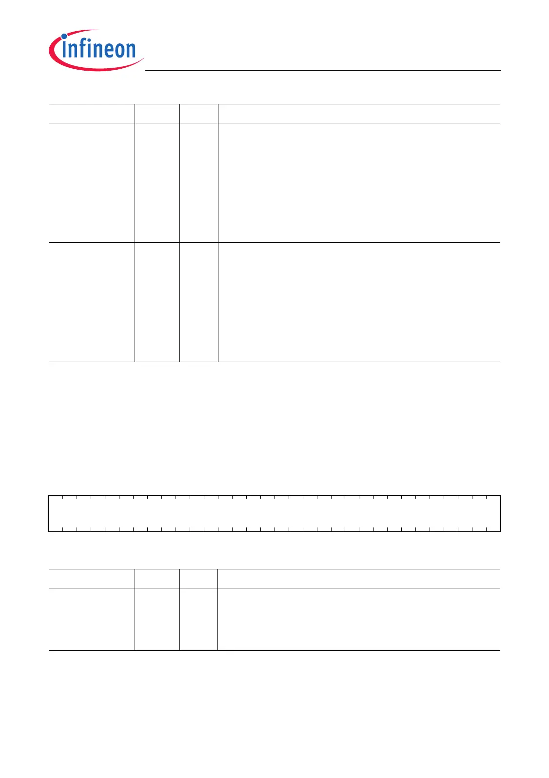
SBCU_DBADRT
SBCU Debug Trapped Address Register
(48
H
) Reset Value: 0000 0000
H
RBCU_DBADRT
RBCU Debug Trapped Address Register
(48
H
) Reset Value: 0000 0000
H
31 0
FPIADR
r
Field Bits Type Description
FPIADR [31:0] r FPI Bus Address Status
This register contains the FPI Bus address that was
captured when the OCDS break trigger event
occurred.
Field Bits Type Description

 Loading...