TC1796
System Units (Vol. 1 of 2)
LMB External Bus Unit
User’s Manual 13-22 V2.0, 2007-07
EBU, V2.0
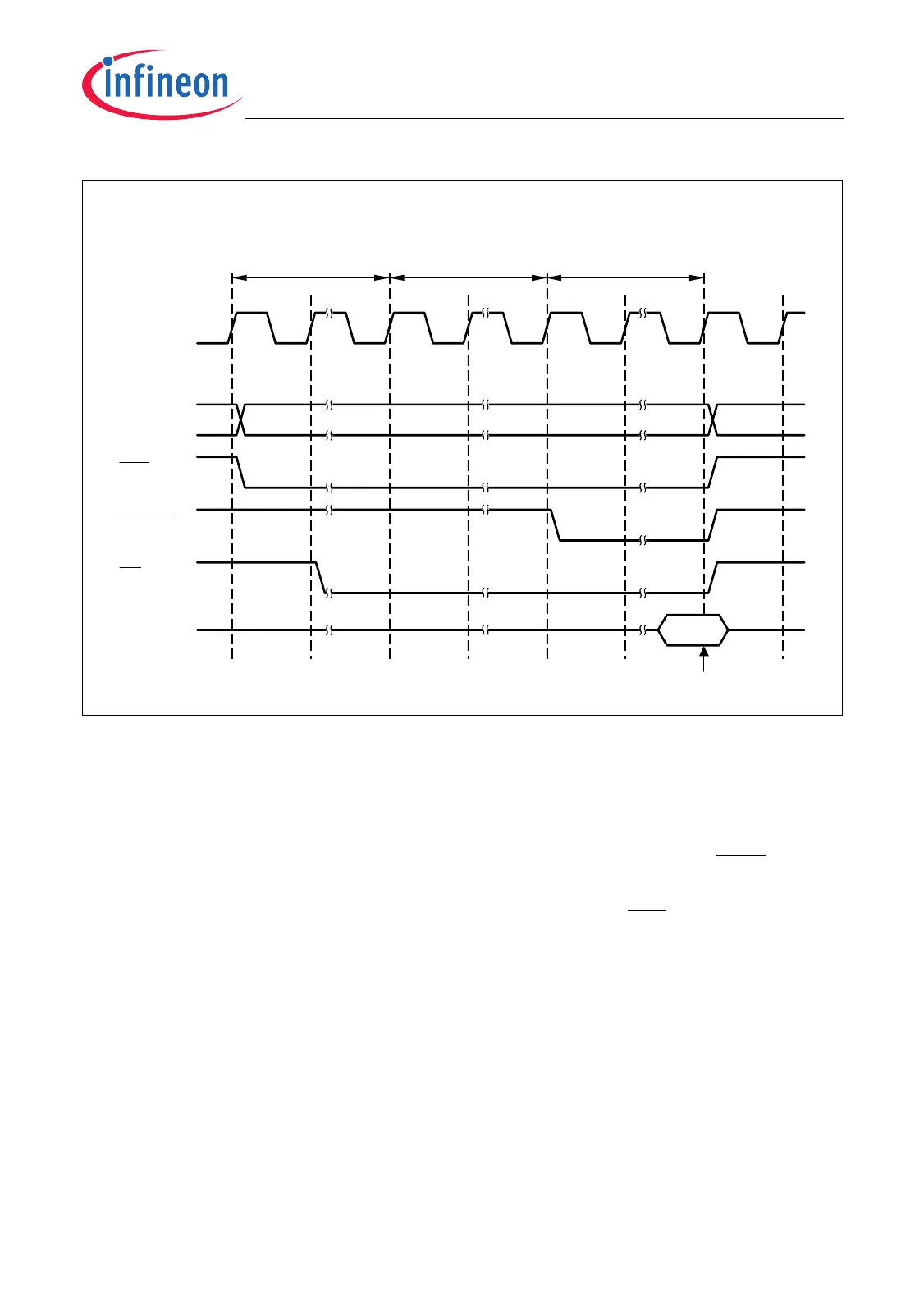
Figure 13-9 Boot Read Access Cycle
When a reset has becomes inactive, the EBU waits for a gap of 256 LMBCLK clock
cycles until the access is initiated, as shown in Figure 13-9. This gap is inserted to fulfill
the recovery times needed by external synchronous devices such as Flash ROMs.
During the read access, the maximum number of programmable LMBCLK cycles is
inserted (WAITRDC × CMULT = 7 × 32 = 224), and the evaluation of the WAIT signal is
inhibited.
Note: The boot memory must be connected to chip select line CS0. The EBU assumes
that the boot memory is 32-bit wide and, therefore, always reads a 32-bit
configuration word at the “Data in” point shown above. The encoding of this 32-bit
configuration word subsequently signals whether the memory is actually 32-bit or
16-bit wide. In the case of 16-bit wide memory, the EBU will discard the most
significant 16 bits of the configuration word.
Note: If FFFF
H
is returned as configuration word during the boot read cycle (e.g. by
reading the configuration word from an erased external boot memory device), the
arbitration mode is set to No Bus Mode (ARBMODE = 00
B
, see “No Bus
Arbitration Mode” on Page 13-10).
Data in
LMBCLK
A[23:0]
000004
H
MCT05720
AP0 AP95 CD0 CD223 CP0
CS0
RD
D[31:0]
CP223
Address Phase
(96 LMB_CLK
cycles)
Command Delay
Phase
(224 LMB_CLK
cycles)
BC[3:0]
Command Phase
(224 LMB_CLK
cycles)
Write Data
to BUSCON
Register
X
Sample
 Loading...