Instruction Set
www.ti.com
1122
SPNU563A–March 2018
Submit Documentation Feedback
Copyright © 2018, Texas Instruments Incorporated
High-End Timer (N2HET) Module
23.6.3.21 SCNT (Step Count)
Syntax SCNT {
[brk={OFF | ON}]
[next={label | 9-bit unsigned integer}]
step={8 | 16 | 32 | 64}
[control={OFF | ON}]
gapstart={25-bit unsigned integer}
[data={25-bit unsigned integer]
}
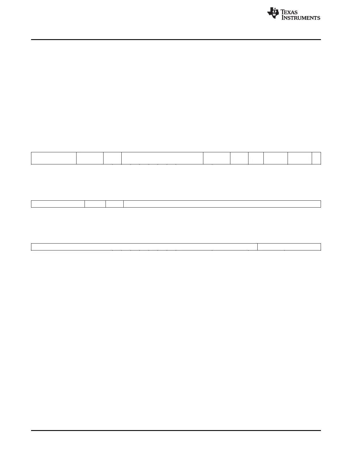
Figure 23-180. SCNT Program Field (P31:P0)
31 26 25 23 22 21 13 12 9 8 7 6 5 4 3 1 0
0 Reserved BRK Next program address 1010 Res. 00 Step
width
Res. 1
6 3 1 9 4 1 2 2 3 1
Figure 23-181. SCNT Control Field (C31:C0)
31 27 26 25 24 0
Reserved Control Res. Gap start
5 1 1 25
Figure 23-182. SCNT Data Field (D31:D0)
31 7 6 0
Data Reserved
25 7
Cycles One or two cycles (two cycles when DF is involved in the calculations)
Register modified Register A
Description This instruction can be used only once in a program and defines a specialized
virtual timer used after APCNT and before ACNT to generate an angle-
referenced time base synchronized to an external signal (that is, a toothed
wheel signal) as defined in APCNT and ACNT. Step width selection bits are
saved in two flags, SWF0, and SWF1, to be re-used in ACNT.
SCNT multiplies the frequency of the external signal by a constant K defined
in the step width field, [P5:P4]. The bit encoding for this field is defined in
Table 23-93.
step Specifies the step increment to be added to the counter value each
program resolution. These two bits provide the values for the SWF0
and SWF1 flags. The valid values are listed in Table 23-93.

 Loading...


