f
RT I FRCx
f
RT I C LK
RTICPUCx + 1
----------------------------------------
when RTICPUCx 0≠
f
RT ICLK
2 +1
32
--------------------
when RTICPUCx = 0
=
{
RTICLK
RTICLK
FlexRay Macrotick (NTU0)
FlexRay Start of Cycle (NTU1)
Counter Block 0
64-bit
incl. FlexRay Feature
Counter Block 1
64-bit
Event0
VIM REQ[2]
DMA REQ[12]
Event1
VIM REQ[3]
DMA REQ[13]
Event2
VIM REQ[4]
DMA REQ[18]
Event3
VIM REQ[5]
DMA REQ[19]
32
32
32
32
32
32
Compare Unit
Capture Feature
Capture Feature
NTU2
NTU3
www.ti.com
Module Operation
585
SPNU563A–March 2018
Submit Documentation Feedback
Copyright © 2018, Texas Instruments Incorporated
Real-Time Interrupt (RTI) Module
17.2 Module Operation
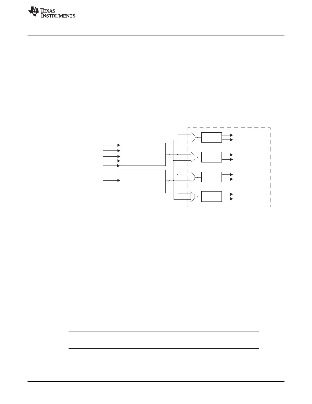
Figure 17-1 illustrates the high level block diagram of the RTI module.
The RTI module has two independent counter blocks for generating different timebases: counter block 0
and counter block 1. The two counter blocks provide the same basic functionality, but counter block 0 has
the additional functionality of being able to work with the FlexRay Macrotick (NTU0) or Start of Cycle
(NTU1) and perform clock supervision to detect a missing signal.
A compare unit compares the counters with programmable values and generates four independent
interrupt or DMA requests on compare matches. Each of the compare registers can be programmed to be
compared to either counter block 0 or counter block 1.
The following sections describe the individual functions in more detail.
Figure 17-1. RTI Block Diagram
17.2.1 Counter Operation
Each counter block consists of the following (see Figure 17-2):
• One 32-bit prescale counter (RTIUC0 or RTIUC1)
• One 32-bit free running counter (RTIFRC0 or RTIFRC1)
The RTIUC0/1 is driven by the RTICLK and counts up until the compare value in the compare up counter
register (RTICPUC0 or RTICPUC1) is reached. When the compare matches, RTIFRC0/1 is incremented
and RTIUC0/1 is reset to 0. If RTIFRC0/1 overflows, an interrupt is generated to the vectored interrupt
manager (VIM). The overflow interrupt is not intended to generate the timebase for the operating system.
See Section 17.2.2 for the timebase generation. The up counter together with the compare up counter
value prescale the RTI clock. The resulting formula for the frequency of the free running counter
(RTIFRC0/1) is:
(23)
NOTE: Setting RTICPUCx equal to zero is not recommended. Doing so will hold the Up Counter at
zero for two RTICLK cycles after it overflows from 0xFFFFFFFF to zero.
The counter values can be determined by reading the respective counter registers or by generating a
hardware event which captures the counter value into the respective capture register. Both functions are
described in the following sections.

 Loading...


