www.ti.com
EMIF Registers
833
SPNU563A–March 2018
Submit Documentation Feedback
Copyright © 2018, Texas Instruments Incorporated
External Memory Interface (EMIF)
21.3.6 SDRAM Timing Register (SDTIMR)
The SDRAM timing register (SDTIMR) is used to program many of the SDRAM timing parameters.
Consult the SDRAM datasheet for information on the appropriate values to program into each field. The
SDTIMR is shown in Figure 21-20 and described in Table 21-30.
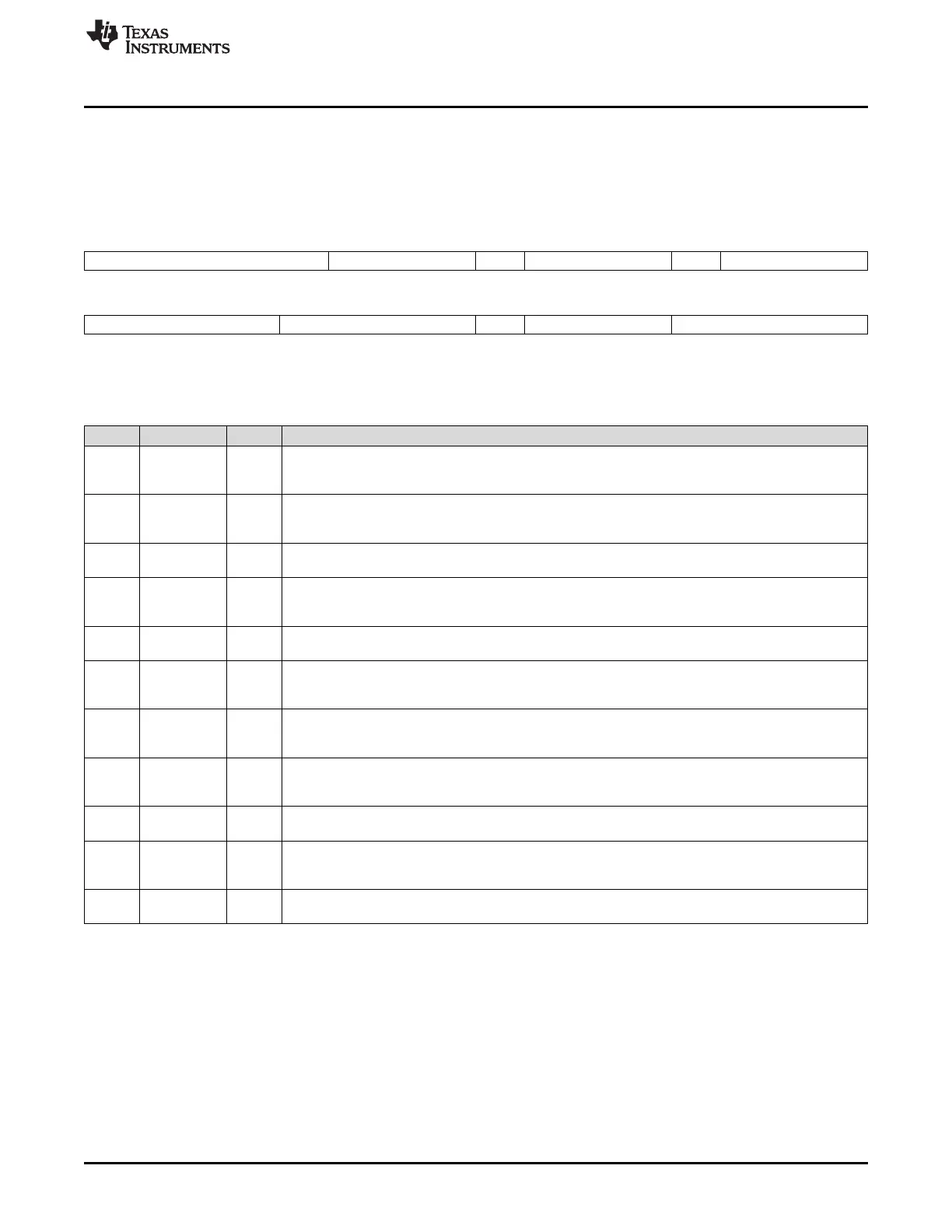
Figure 21-20. SDRAM Timing Register (SDTIMR) [offset = 20h]
31 27 26 24 23 22 20 19 18 16
T_RFC T_RP Rsvd T_RCD Rsvd T_WR
R/W-8h R/W-2h R-0 R/W-2h R-0 R/W-1h
15 12 11 8 7 6 4 3 0
T_RAS T_RC Rsvd T_RRD Reserved
R/W-5h R/W-8h R-0 R/W-1h R-0
LEGEND: R/W = Read/Write; R = Read only; -n = value after reset
Table 21-30. SDRAM Timing Register (SDTIMR) Field Descriptions
Bit Field Value Description
31-27 T_RFC 0-1Fh Specifies the Trfc value of the SDRAM. This defines the minimum number of EMIF_CLK cycles from
Refresh (REFR) to Refresh (REFR), minus 1:
T_RFC = (Trfc/t
EMIF_CLK
) - 1
26-24 T_RP 0-7h Specifies the Trp value of the SDRAM. This defines the minimum number of EMIF_CLK cycles from
Precharge (PRE) to Activate (ACTV) or Refresh (REFR) command, minus 1:
T_RP = (Trp/t
EMIF_CLK
) - 1
23 Reserved 0 Reserved. The reserved bit location is always read as 0. If writing to this field, always write the default
value of 0.
22-20 T_RCD 0-7h Specifies the Trcd value of the SDRAM. This defines the minimum number of EMIF_CLK cycles from
Active (ACTV) to Read (READ) or Write (WRT), minus 1:
T_RCD = (Trcd/t
EMIF_CLK
) - 1
19 Reserved 0 Reserved. The reserved bit location is always read as 0. If writing to this field, always write the default
value of 0.
18-16 T_WR 0-7h Specifies the Twr value of the SDRAM. This defines the minimum number of EMIF_CLK cycles from
last Write (WRT) to Precharge (PRE), minus 1:
T_WR = (Twr/t
EMIF_CLK
) - 1
15-12 T_RAS 0-Fh Specifies the Tras value of the SDRAM. This defines the minimum number of EMIF_CLK clock cycles
from Activate (ACTV) to Precharge (PRE), minus 1:
T_RAS = (Tras/t
EMIF_CLK
) - 1
11-8 T_RC 0-Fh Specifies the Trc value of the SDRAM. This defines the minimum number of EMIF_CLK clock cycles
from Activate (ACTV) to Activate (ACTV), minus 1:
T_RC = (Trc/t
EMIF_CLK
) - 1
7 Reserved 0 Reserved. The reserved bit location is always read as 0. If writing to this field, always write the default
value of 0.
6-4 T_RRD 0-7h Specifies the Trrd value of the SDRAM. This defines the minimum number of EMIF_CLK clock cycles
from Activate (ACTV) to Activate (ACTV) for a different bank, minus 1:
T_RRD = (Trrd/t
EMIF_CLK
) - 1
3-0 Reserved 0 Reserved. The reserved bit location is always read as 0. If writing to this field, always write the default
value of 0.

 Loading...


