7
CAPEVT0
CAPEVTSRC0[6:0]
7
CAPEVT1
CAPEVTSRC1[6:0]
INT_REQ0
INT_REQ1
INT_REQ126
INT_REQ127
INT_REQ0
INT_REQ1
INT_REQ126
INT_REQ127
To RTI To RTI
www.ti.com
Capture Event Sources
677
SPNU563A–March 2018
Submit Documentation Feedback
Copyright © 2018, Texas Instruments Incorporated
Vectored Interrupt Manager (VIM) Module
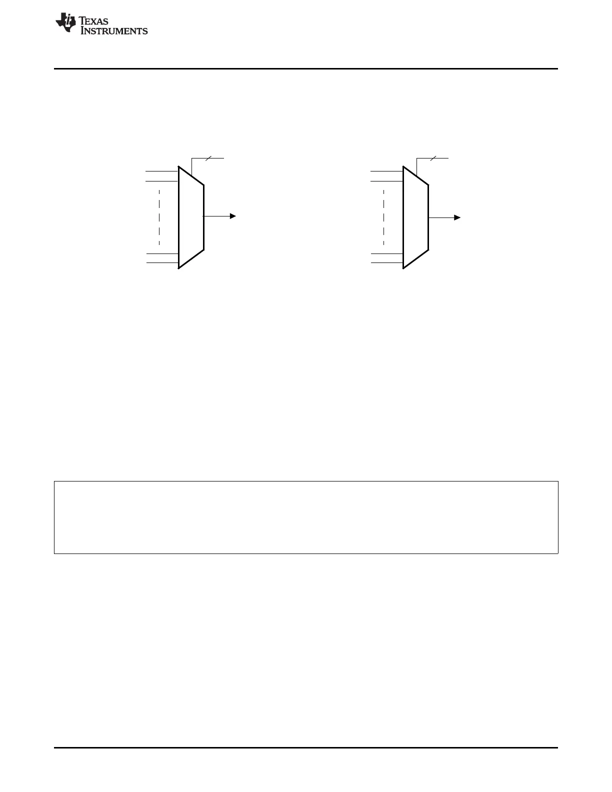
19.7 Capture Event Sources
The VIM can select any of the 128 interrupt request to generate up to two capture events for the real-time
interrupt (RTI) module (see Figure 19-11). The value in REQENASET / REQENACLR does NOT impact
the capture event. Two registers (Section 19.9.17) are available, one for each capture event source.
Figure 19-11. Capture Event Sources
19.8 Examples
The following sections provide examples about the operation of the VIM.
19.8.1 Examples - Configure CPU To Receive Interrupts
Example 19-1 shows how to set the vector enable (VE) bit in the CP15 R1 register to enable the hardware
vector interrupt. Example 19-2 shows how to enable/disable the IRQ and FIQ through CPSR. As a
convention, the program who calls these subroutines shall preserve register R1 if needed. Example 19-2
can ONLY run in privileged mode. However, in USER mode, the application software can force the
program into software interrupt by instruction ‘SWI’. Then, in the software interrupt service routine, user
can write register SPSR, which is the copy of CPSR in this exception mode.
Example 19-1. Enable Hardware Vector Interrupt (IRQ Only)
_HW_Vec_Init
MRC p15 ,#0 ,R1 ,c1 ,c0 ,#0
ORR R1 ,R1 ,#0x01000000 ; Mask 0-31 bits except bit 24 in Sys
; Ctrl Reg of CORTEX-R4
MCR p15 ,#0 ,R1 ,c1 ,c0 ,#0 ; Enable bit 24
MOV PC, LR

 Loading...


