EMIF_nCS[0]
EMIF_nCAS
EMIF_nRAS
EMIF_CLK
EMIF_CKE
EMIF_nCS[4:2]
EMIF_nOE
EMIF_nWAIT
EMIF_nWE
EMIF_BA[1:0]
EMIF_nDQM[1:0]
EMIF_DATA[15:0]
EMIF_ADDR[21:0]
EMIF
CPU
EDMA
Master
Peripherals
SDRAM
interface
Asynchronous
interface
Shared SDRAM
and asynchronous
interface
www.ti.com
Introduction
795
SPNU563A–March 2018
Submit Documentation Feedback
Copyright © 2018, Texas Instruments Incorporated
External Memory Interface (EMIF)
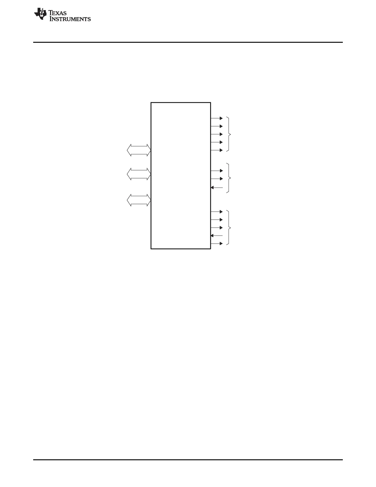
21.1.3 Functional Block Diagram
Figure 21-1 illustrates the connections between the EMIF and its internal requesters, along with the
external EMIF pins. Section 21.2.2 contains a description of the entities internal to the SoC that can send
requests to the EMIF, along with their prioritization. Section 21.2.3 describes the EMIF external pins and
summarizes their purpose when interfacing with SDRAM and asynchronous devices.
Figure 21-1. EMIF Functional Block Diagram

 Loading...


