][4
5
][20
][5
4
][20
MHz
MHz
NR
f
orMHz
MHz
NR
f
CLKINCLKIN
====
Modulation Period (1/f
s
)
Modulation
f
f
0
0
-n%
f
0
+n%
Time (Ps)
Frequency (MHz)
Depth
Phase-Locked Loop Theory of Operation
www.ti.com
540
SPNU563A–March 2018
Submit Documentation Feedback
Copyright © 2018, Texas Instruments Incorporated
Oscillator and PLL
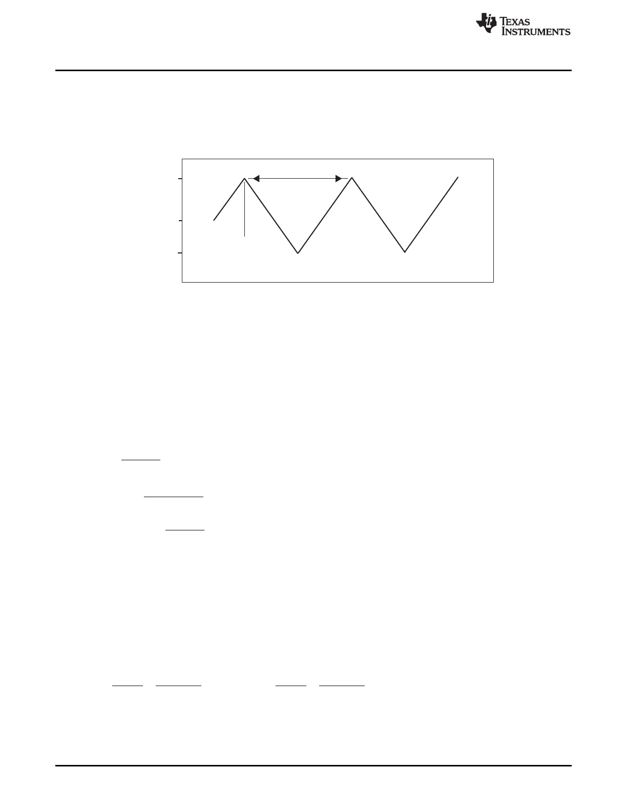
14.7.4 Frequency Modulation
The output clock of the PLL changes frequency in a controlled way, centered around the unmodulated
output frequency. The modulation block directly modulates the VCO frequency at the loop filter, and
creates the triangular frequency modulation (see Figure 14-12).
Figure 14-12. Frequency versus Time
14.8 Programming Example
This section provides an example of how to program the PLL. For non-modulation settings, the PLLCTL1
and PLLCTL2 settings from 130nm process devices can be used without modification.
Suppose that, using a 20 MHz crystal, the application requires:
• 180 MHz GCLK1 (and HCLK) frequency
• 100 kHz spreading frequency
• 0.5% spreading depth
1. Choose an NR and NS such that:
• (14)
• (15)
• (16)
• (NR,NS) = {(5,20), (4,25), (2,50), (1,100)}
• Either NR = 5 and NS = 20 or NR = 4 and NS = 25 are reasonable. Another choice (NR = 3 and
NS = 33) is possible, if the modulation frequency can vary from 100 KHz.
2. Choose Output CLK frequency as integer divider of output frequency near to 330 MHz. Output CLK
frequency shall not exceed 550 MHz or fall below 150 MHz.
The integer values for 180 MHz are 360 MHz or 540 MHz. 360 MHz is close to the target frequency of
330 MHz and we use this frequency.
3. In this case, either of the following equations are suitable choices for getting to 360 MHz.
Choose NR = 5, NS = 20 and set NF = 90 or choose NR = 4, NS = 25 and set NF = 72.
(17)
4. Select the output divider OD so that the post-ODCLK frequency does not exceed the maximum
frequency of output divider R (device-specific frequency). In this case, choose OD = 2 and R = 1.

 Loading...


