GTUC2.MPC = m
GTUC4.NIT = k
GTUC4.OCS = NIT+1
Static / Dynamic Segment
Symbol Window
NIT
0
n
n+1 k
k+1
m+1
www.ti.com
Module Operation
1227
SPNU563A–March 2018
Submit Documentation Feedback
Copyright © 2018, Texas Instruments Incorporated
FlexRay Module
Parameters: Symbol Window Action Point Offset GTUC9.APO(4-0) (same as for static slots), Network
Idle Time Start GTUC4.NIT(13-0)
26.2.2.4 Network Idle Time (NIT)
During network idle time the communication controller has to perform the following tasks:
• Calculate clock correction terms (offset and rate)
• Distribute offset correction over multiple macroticks after offset correction start
• Perform cluster cycle related tasks
Parameters: network idle time start GTUC4.NIT(13-0), offset correction start GTUC4.OCS(13-0)
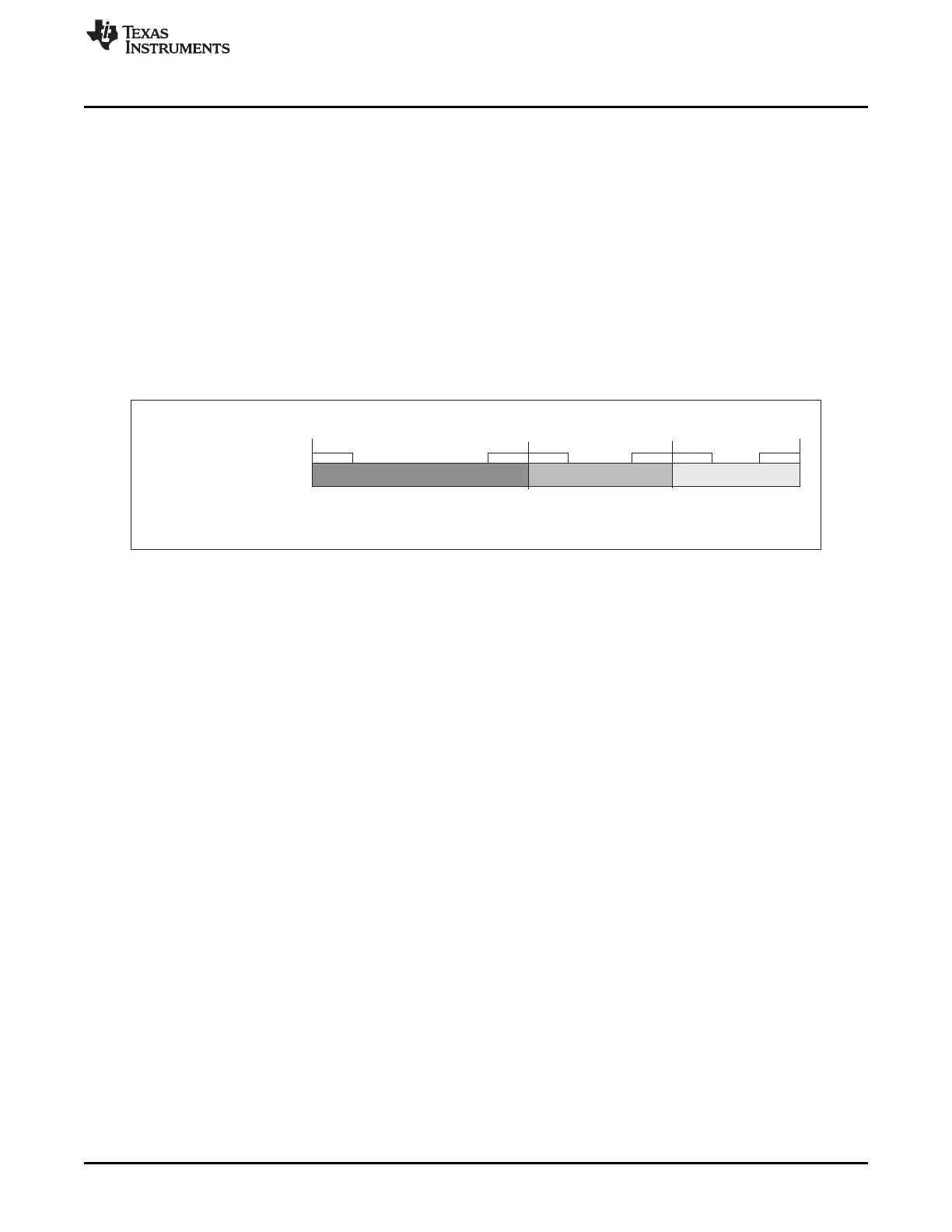
26.2.2.5 Configuration of NIT Start and Offset Correction Start
Figure 26-11. Configuration of NIT Start and Offset Correction Start
The number of macroticks per cycle is assumed to be m. It is configured by programming GTUC2.MPC =
m in the GTU Configuration register 2.
The static / dynamic segment starts with macrotick 0 and ends with macrotick n: n = static segment length
+ dynamic segment offset + dynamic segment length - 1MT
The static segment length is configured by GTUC7.SSL and GTUC7.NSS. The dynamic segment length is
configured by GTUC8.MSL and GTUC8.NMS.
The dynamic segment offset is ActionPointOffset - MinislotActionPointOffset or 0 MT if the result is
negative. For details, refer to the FlexRay Communications System Protocol Specification from the
FlexRay Consortium.
The NIT starts with macrotick k+1 and ends with the last macrotick of cycle m-1. It has to be configured by
setting GTUC4.NIT = k.
For this FlexRay module the offset correction start is required to be GTUC4.OCS >= GTUC4.NIT + 1 =
k+1.
The length of symbol window results from the number of macroticks between the end of the static /
dynamic segment and the beginning of the NIT. It can be calculated by k - n.
26.2.3 Communication Modes
The FlexRay protocol specification v2.1 Rev. A defines the Time-Triggered Distributed (TT-D) mode.
26.2.3.1 Time-Triggered Distributed (TT-D)
In TT-D mode the following configurations are possible:
• Pure static: minimum 2 static slots + symbol window (optional)
• Mixed static/dynamic: minimum 2 static slots + dynamic segment + symbol window (optional)
A minimum of two coldstart nodes need to be configured for distributed time-triggered operation. Two
fault-free coldstart nodes are necessary for the cluster startup. Each startup frame must be a sync frame,
therefore all coldstart nodes are sync nodes.

 Loading...


