GIO Control Registers
www.ti.com
1206
SPNU563A–March 2018
Submit Documentation Feedback
Copyright © 2018, Texas Instruments Incorporated
General-Purpose Input/Output (GIO) Module
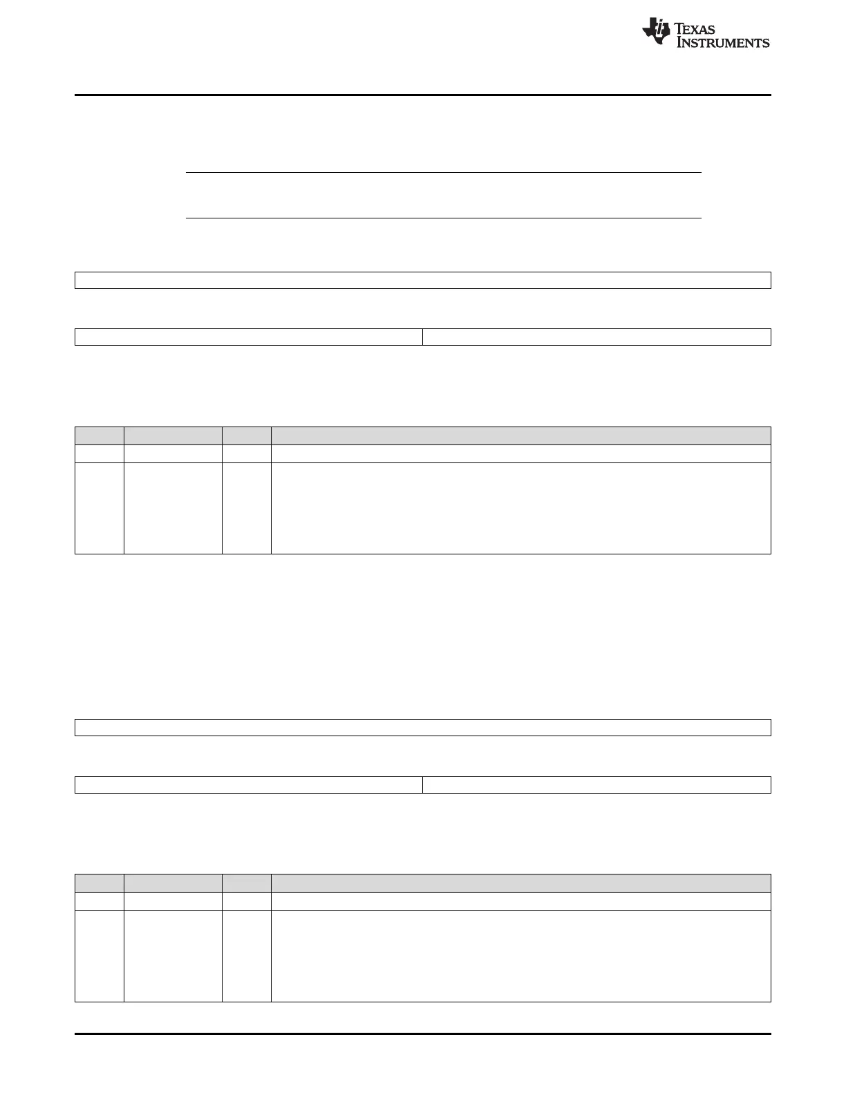
25.5.13 GIO Data Output Registers (GIODOUT[A-B])
Values in the GIODOUT register specify the output state (high = 1 or low = 0) of the pins of the port when
they are configured as outputs. Figure 25-19 and Table 25-16 describe this register.
NOTE: Values in the GIODSET register set the data output control register bits to 1 regardless of
the current value in the GIODOUT bits.
Figure 25-19. GIO Data Output Registers (GIODOUT[A-B]) [offset = 3Ch, 5Ch]
31 16
Reserved
R-0
15 8 7 0
Reserved GIODOUT[7:0]
R-0 R/W-0
LEGEND: R/W = Read/Write; R = Read only; -n = value after reset
Table 25-16. GIO Data Output Registers (GIODOUT[A-B]) Field Descriptions
Bit Field Value Description
31-8 Reserved 0 Reads return 0. Writes have no effect.
7-0 GIODOUT[n] GIO data output of port n, pins[7:0].
0 The pin is driven to logic low (0).
1 The pin is driven to logic high (1).
Note: Output is in high impedance state if the GIOPDRx bit = 1 and GIODOUTx bit = 1.
Note: GIO pin is placed in output mode by setting the GIODIRx bit to 1.
25.5.14 GIO Data Set Registers (GIODSET[A-B])
Values in this register set the data output control register bits to 1 regardless of the current value in the
GIODOUT bits. The contents of this register reflect the contents of GIODOUT. Figure 25-20 and Table 25-
17 describe this register.
Figure 25-20. GIO Data Set Registers (GIODSET[A-B]) [offset = 40h, 60h]
31 16
Reserved
R-0
15 8 7 0
Reserved GIODSET[7:0]
R-0 R/W-0
LEGEND: R/W = Read/Write; R = Read only; -n = value after reset
Table 25-17. GIO Data Set Registers (GIODSET[A-B]) Field Descriptions
Bit Field Value Description
31-8 Reserved 0 Reads return 0. Writes have no effect.
7-0 GIODSET[n] GIO data set for port n, pins[7:0]. This bit drives the output of GIO pin high.
0 Write: Writing a 0 has no effect.
1 Write: The corresponding GIO pin is driven to logic high (1).
Note: The current logic state of the GIODOUT bit will also be displayed by this bit.
Note: GIO pin is placed in output mode by setting the GIODIRx bit to 1.

 Loading...


