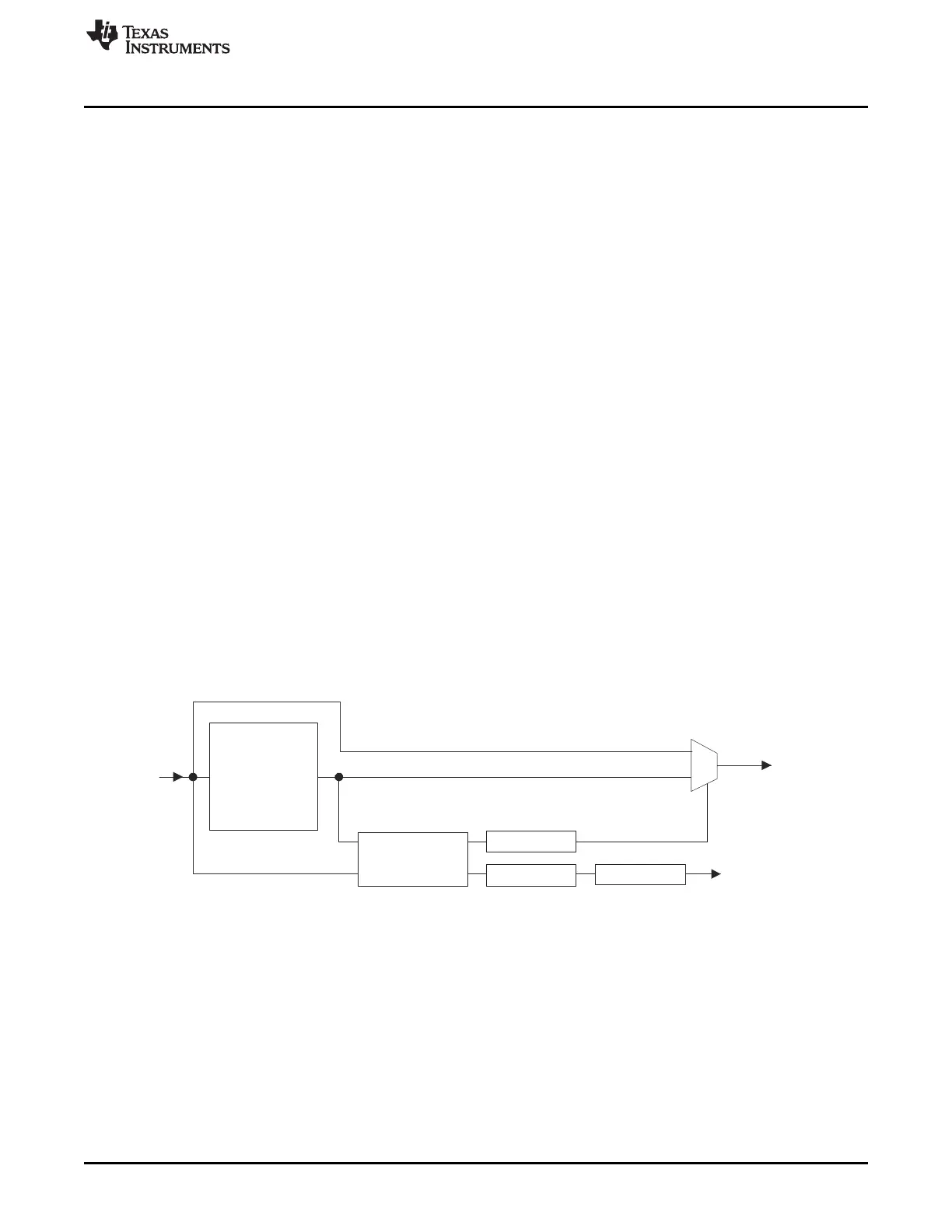
PLL Bypass CLK
PLL CLK
Input from
Oscillator
CLK signal to
Clock Control Module
Slip Detector
BPOS
BPOS
FMzPLL
ROS
To Device Reset
Bypass on Slip
Reset on Slip
www.ti.com
PLL
531
SPNU563A–March 2018
Submit Documentation Feedback
Copyright © 2018, Texas Instruments Incorporated
Oscillator and PLL
14.5.3 Behavior on PLL Fail
The PLL allows flexible response to a PLL failure (slip). Like the oscillator, the PLL clock is configured by
default to automatically switch-over to the oscillator in case of a PLL slip. (In this case, the oscillator
sources GCM clock source 1 as well as GCM clock source 0. Also, if the oscillator fails, LPO HF is
sourced to both GCM clock sources 0 and 1.)
The PLL slip outputs indicate that the PLL is running either too fast or too slow. These error output toggle
when the PLL is locking and when the PLL is disabling. The PLL blocks these slip outputs during these
times, leaving them active only while the PLL is active.
A slip after the PLL has locked and while it is active is an indication of a PLL failure. The PLL provides
slip-filtering which enhances the flexibility of the PLL’s response to failure. The slip-filtering circuit samples
the slip based on HF LPO. The filter defines the number of consecutive HF LPO cycles for which the slip
signal must be active before the slip is recognized. This slip is latched in the RFSLIP and FBSLIP status
flags in the Global Status Register (GLBSTAT) of the System and Peripheral Control Registers.
The PLL may enable/disable the automatic switch over as well as the error signaling; if the error signaling
is enabled, a PLL slip may be configured to generate a reset. The automatic switch-over and suppression
of the error signals are controlled by the bypass on slip bit field -- BPOS[1:0] (PLLCTL1.(30:29)). When
BPOS[1:0] is disabled (BPOS[1:0] = 10b):
• automatic response to the PLL slip is prevented
• ESM/exception is NOT generated
• reset on slip is not generated regardless of the state of the ROS bit
• status bits are set on a PLL slip independent of BPOS[1:0]
When BPOS[1:0] is enabled (BPOS[1:0] = 00b OR 01b OR 11b):
• PLL slip causes the clock source into GCM clock source 1 to shift from the PLL to the oscillator
• ESM/exception is generated
• reset on slip is generated if ROS is set
The effect of BPOS[1:0] on the system is shown in Figure 14-5.
Figure 14-5. PLL Slip Detection and Reset/Bypass Block Diagram

 Loading...


