www.ti.com
STC Control Registers
447
SPNU563A–March 2018
Submit Documentation Feedback
Copyright © 2018, Texas Instruments Incorporated
Self-Test Controller (STC) Module
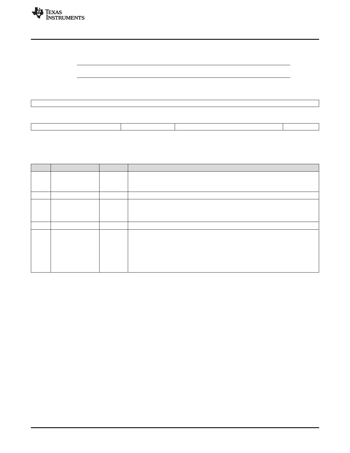
10.8.1 STC Global Control Register 0 (STCGCR0)
This register is described in Figure 10-8 and Table 10-9.
NOTE: On a power-on reset or system reset, this register gets reset to its default values.
Figure 10-8. STC Global Control Register 0 (STCGCR0) [offset = 00h]
31 16
INTCOUNT
R/WP-1
15 11 10 8 7 2 1 0
Reserved CAP_IDLE_CYCLE Reserved RS_CNT
R-0 R/WP-1 R-0 R/WP-0
LEGEND: R/W = Read/Write; R = Read only; WP = Write in privilege mode only; -n = value after reset
Table 10-9. STC Global Control Register 0 (STCGCR0) Field Descriptions
Bit Field Value Description
31-16 INTCOUNT Number of intervals of self-test run.
0-FFFFh This register specifies the number of intervals to run for the self-test run. This corresponds
to the number of intervals to be run from the value reflected in the current interval counter.
15-11 Reserved 0 Reads return 0. Writes have no effect.
10-8 CAP_IDLE_CYCLE Idle cycle before and after the capture clock.
0 Disabled
1 Enabled
7-2 Reserved 0 Reads return 0. Writes have no effect.
1-0 RS_CNT Restart or Continue
This bit specifies whether to continue the run from next interval onwards or to restart from
interval 0. This bit gets reset after the completion of a self-test run.
0 Continue STC run from the previous interval.
1h Restart STC run from interval 0.
2h-3h Reserved

 Loading...


