Interrupt Vector Table (VIM RAM)
www.ti.com
674
SPNU563A–March 2018
Submit Documentation Feedback
Copyright © 2018, Texas Instruments Incorporated
Vectored Interrupt Manager (VIM) Module
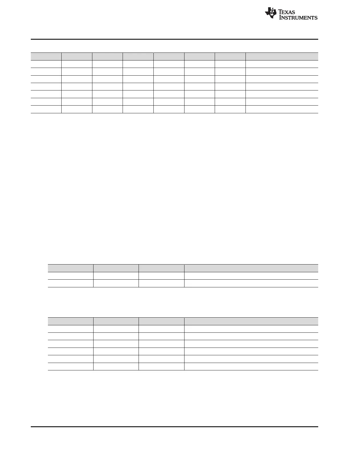
Table 19-2. ECC Error Bits for Syndrome Decode
6 5 4 3 2 1 0 ECC
x 6
x 5
x 4
x 3
x 2
x 1
x 0
19.5.3 Interrupt Vector Table Initialization
After reset, the interrupt vector table content, including the ECC bits is not initialized. Therefore, the
interrupt vector table has to be initialized first before enabling the corresponding interrupt channel. This
can be done either using the hardware initialization mechanism (in Chapter Architecture Overview) or it
can be done by writing known values into the interrupt vector table by software. If ECC is required, this
initialization should be done after the ECC functionality is enabled. In this way, the corresponding ECC
bits will be automatically updated. This initialization is only required when vectored interrupts are used,
index interrupt management does not need the table to be initialized.
19.5.4 Interrupt Vector Table ECC Testing
To test the ECC checking mechanism, the ECC bits allows manual insertion of faults. This option is
implemented using the TEST_DIAG_EN bit in the ECCCTL register control bit. Once TEST_DIAG_EN is
enabled, the ECC bits are mapped to 0xFFF82400. In this mode, the user can modify the ECC bits
without changing the data bits. If ECCENA is disabled, writing to data bits does not automatically update
ECC bits. The CPU reads and writes under different conditions are summarized in Table 19-3 and
Table 19-4. After that, user can force faults into either the data or the ECC bits. Finally, the ECC error can
be triggered by reading interrupt vector table (not ECC bits) from VIM or CPU. Please note that no ECC
checking will be done for reads of ECC bits in test mode.
Table 19-3. CPU Reads - Address Bit 10 Selects Between Normal Data and ECC Bits
VBUSP_ ADDR(10) TEST_DIAG_ EN ECCENA Action
0 x(don’t care) x(don’t care) Normal RAM location read
1 x x ECC bits read
Table 19-4. CPU Writes - Address Bit 10 Selects Between Normal Data and ECC Bits
VBUSP_ ADDR(10) TEST_DIAG_ EN ECCENA Action
0 x 1 Normal RAM locations write with ECC bits
1 0 1 This write will be blocked
1 1 1 ECC bits write
0 x 0 Normal RAM locations write without ECC bits
1 0 0 This write will be blocked
1 1 0 This write is not allowed

 Loading...


