SCR
IA0 IA1 IA_n
TA0
TA_m
SCM
req2accept
req2resp
req2accept
req2resp
req2accept
req2resp
To_clear
Dtc_soft_reset (3:0)
Global_error_clr
active_ia_o(n-1:0)
err_event
Sdc_test_finished
Hwchkr_sdc_soft_reset
clkstopppedm_0/1
acpidle
Parity_diagnostic_enable
active_ta_o(m-1:0)
Overview
www.ti.com
254
SPNU563A–March 2018
Submit Documentation Feedback
Copyright © 2018, Texas Instruments Incorporated
SCR Control Module (SCM)
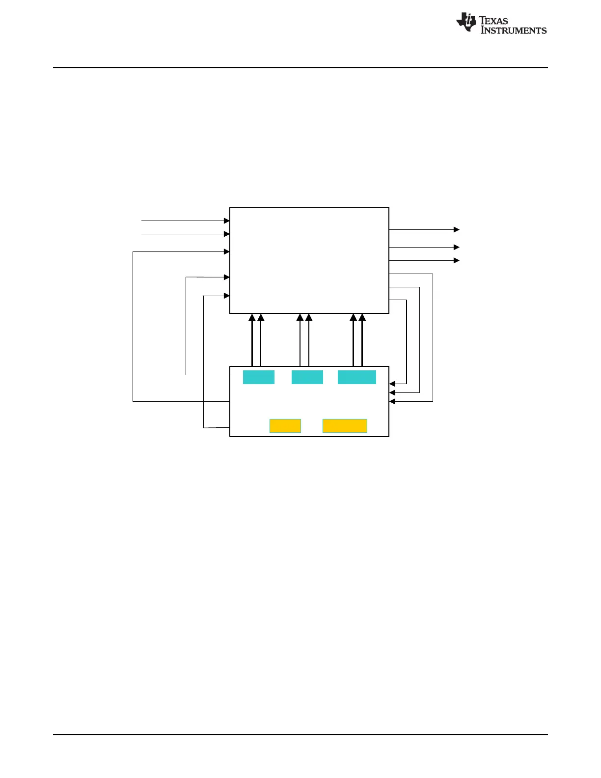
3.1.2 System Block Diagram
Figure 3-1 shows the system level block diagram of SCM and interconnect (SCR).
SCM compares the transaction command request to transaction command accept (req2accept) counters
and transaction command request to transaction command response (req2resp) counters of each initiator
agent (IA) to the corresponding threshold values (programmable). If the req2accept or req2resp counters
are larger than or equal to the threshold, SCM will generate error event to ESM module.
SCM can clear the req2accept and req2resp counters inside interconnect SCR. It can also initiate self-test
sequence to make sure the hardware checker diagnostic logic is functioning properly.
Figure 3-1. System Level Block Diagram
n is the maximum number of IA. m is the maximum number of TA.

 Loading...


