VIM Control Registers
www.ti.com
694
SPNU563A–March 2018
Submit Documentation Feedback
Copyright © 2018, Texas Instruments Incorporated
Vectored Interrupt Manager (VIM) Module
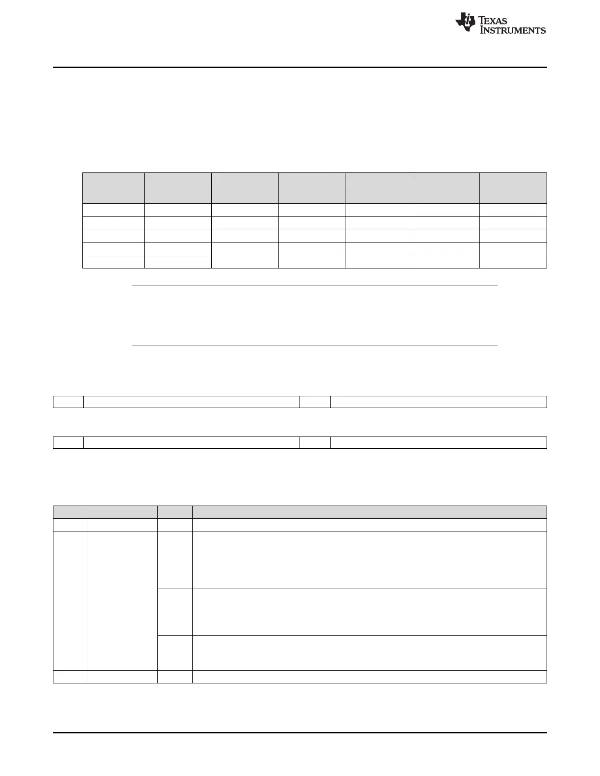
19.9.18 VIM Interrupt Control Registers (CHANCTRL[0:31])
Thirty-two interrupt control registers control the 128 interrupt channels of the VIM. Each register controls
four interrupt channels: each of them is indexed from 0 to 127. Table 19-23 shows the organization of all
the registers and the reset value of each. Each four fields of the register has been named with a generic
index that refers to the detailed register organization. Figure 19-46 and Table 19-24 describe these
registers.
Table 19-23. Interrupt Control Registers Organization
Address
Register
Acronym
Register Field
31:24
CHANMAPx
0
Register Field
23:16
CHANMAPx
1
Register Field
15:8
CHANMAPx
2
Register Field
7:0
CHANMAPx
3
Reset Value
FFFF FE80h CHANCTRL0 CHANMAP0 CHANMAP1 CHANMAP2 CHANMAP3 0001 0203h
FFFF FE84h CHANCTRL1 CHANMAP4 CHANMAP5 CHANMAP6 CHANMAP7 0405 0607h
: : : : : : :
FFFF FEF8h CHANCTRL30 CHANMAP120 CHANMAP121 CHANMAP122 CHANMAP123 7879 7A7Bh
FFFF FEFCh CHANCTRL31 CHANMAP124 CHANMAP125 CHANMAP126 CHANMAP127 7C7D 7E7Fh
NOTE: CHANMAP0 and CHANMAP1 are not programable. CHAN0 and CHAN1 are hard wired to
INT_REQ0 and INT_REQ1.
Do NOT write any value other than 0x7F to CHANMAP127. Channel 127 is reserved
because no interrupt vector table entry supports this channel.
Figure 19-46. Interrupt Control Registers (CHANCTRL[0:31])
[offset = 80h-FCh]
31 30 24 23 22 16
Rsvd CHANMAPx
0
Rsvd CHANMAPx
1
R-U R/WP-n R-U R/WP-n
15 14 8 7 6 0
Rsvd CHANMAPx
2
Rsvd CHANMAPx
3
R-U R/WP-n R-U R/WP-n
LEGEND: R = Read only; WP = Write in privilege mode only; U = value is undefined; -n = value after reset (see Table 19-23)
Table 19-24. Interrupt Control Registers (CHANCTRL[0:31]) Field Descriptions
Bit Field Value Description
31 Reserved 0 Reads are indeterminate and writes have no effect.
30-24 CHANMAPx
0
CHANMAPx
0
(6-0). Interrupt CHANx
0
mapping control. These bits determine which interrupt request
the priority channel CHANx
0
maps to:
0 Read: Interrupt request 0 maps to channel priority CHANx
0
.
Write: The default value of this bit after reset is given in Table 19-23 . The channel priority CHANx
0
is set with the interrupt request.
1h Read: Interrupt request 1 maps to channel priority CHANx
0
.
Write: The default value of this bit after reset is given in Table 19-23. The channel priority CHANx
0
is set with the interrupt request.
: :
7Fh Read: Interrupt request 127 maps to channel priority CHANx
0
.
Write: The default value of this bit after reset is given in Table 19-23. The channel priority CHANx
0
is set with the interrupt request.
23 Reserved 0 Reads are indeterminate and writes have no effect.

 Loading...


