START
WR/RD = 1
Busy = 0
Busy = 1
Read message object to IF1/IF2
Write IF1/IF2 to message RAM
Read message object to IF1/IF2
No Yes
Write message number to command register
No
Yes
Message Interface Register Sets
www.ti.com
1434
SPNU563A–March 2018
Submit Documentation Feedback
Copyright © 2018, Texas Instruments Incorporated
Controller Area Network (DCAN) Module
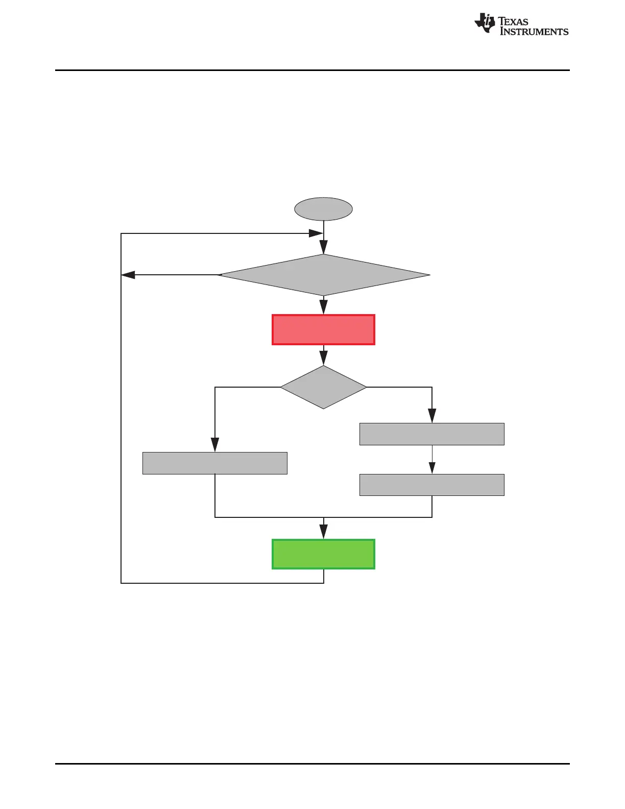
27.6.2 Using Message Interface Register Sets 1 and 2
The Command Register addresses the desired message object in the Message RAM and specifies
whether a complete message object or only parts should be transferred. The data transfer is initiated by
writing the message number to the bits [7:0] of the Command Register.
When the CPU initiates a data transfer between the IF1/IF2 Registers and Message RAM, the Message
Handler sets the Busy bit in the respective Command Register to ‘1’. After the transfer has completed, the
Busy bit is set back to ‘0’ (see Figure 27-8).
Figure 27-8. Data Transfer Between IF1 / IF2 Registers and Message RAM

 Loading...


