www.ti.com
DCC Control Registers
553
SPNU563A–March 2018
Submit Documentation Feedback
Copyright © 2018, Texas Instruments Incorporated
Dual-Clock Comparator (DCC) Module
15.4.6 DCC Status Register (DCCSTAT)
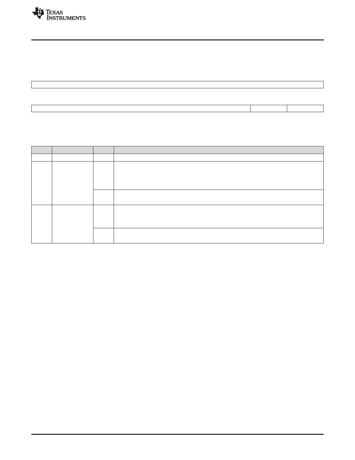
Figure 15-7 and Table 15-2 describe the DCC Status register.
Figure 15-12. DCC Status Register (DCCSTAT) [offset = 14h]
31 16
Reserved
R-0
15 2 1 0
Reserved DONE ERR
R-0 R/W1CP-0 R/W1CP-0
LEGEND: R/W = Read/Write; R = Read only; W1CP = Write 1 to clear in privilege mode only; -n = value after reset
Table 15-7. DCC Status Register (DCCSTAT) Field Descriptions
Bit Field Value Description
31-2 Reserved 0 Reads return 0. Writes have no effect.
1 DONE Single-Shot Sequence Done flag. Indicates that a single-shot DCC sequence is done without any
error.
0 Read: Single-shot sequence is not done.
Write: Writing 0 has no effect.
1 Read: Single-shot sequence is done without any error.
Write: Writing 1 in privileged mode clears the DONE flag.
0 ERR Error flag. Indicates that a DCC error has occurred.
0 Read: DCC error has not occurred.
Write: Writing 0 has no effect.
1 Read: An error has occurred.
Write: Writing 1 in privileged mode clears the ERR flag.

 Loading...


